2NR-FE BATTERY / CHARGING GENERATOR INSTALLATION
PROCEDURE

 27060
1.INSTALL GENERATOR WITH REGULATOR ASSEMBLY
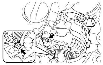
Install the generator with regulator assembly to the cylinder block sub-assembly with the 2 bolts.
- Torque:
- Bolt A : 54 N*m (551 kgf*cm, 40 ft.*lbf)
- Torque:
- Bolt B : 21 N*m (214 kgf*cm, 15 ft.*lbf)
2.INSTALL WIRING HARNESS CLAMP BRACKET
Install the wiring harness clamp bracket to the generator with regulator assembly with the bolt.
- Torque:
- 8.4 N*m (86 kgf*cm, 74 in.*lbf)
82121
3.CONNECT ENGINE WIRE
Install the engine wire to the terminal B with the nut.
- Torque:
- 9.8 N*m (100 kgf*cm, 87 in.*lbf)
Engage the 2 clamps to connect the engine wire to the wiring harness clamp bracket.
Connect the generator with regulator assembly connector.
Install the terminal cap.
Engage the 3 clamps to connect the engine wire to the upper radiator support.
17167
4.INSTALL NO.1 EXHAUST MANIFOLD HEAT INSULATOR
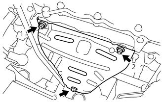
Install the No. 1 exhaust manifold heat insulator to the exhaust manifold converter sub-assembly with the 2 nuts and bolt.
Tighten the 2 nuts and bolt in the order shown in the illustration.
- Torque:
- 7.5 N*m (76 kgf*cm, 66 in.*lbf)
11452
5.INSTALL OIL LEVEL DIPSTICK GUIDE
Apply engine oil to a new O-ring.
Install the O-ring to the oil level dipstick guide.
- NOTICE:
-
Do not twist the O-ring.
Install the oil level dipstick guide to the camshaft housing sub-assembly and oil pan sub-assembly with the bolt.
- Torque:
- 10 N*m (102 kgf*cm, 7 ft.*lbf)
- NOTICE:
-
Make sure that the O-ring is not damaged or does not jump out of position during installation.
Engage the clamp to connect the engine wire to the oil level dipstick guide.
15301
6.INSTALL OIL LEVEL DIPSTICK SUB-ASSEMBLY
Install the oil level dipstick sub-assembly to the oil level dipstick guide.
12611
7.INSTALL NO. 1 ENGINE COVER
for Manual Transaxle: Click hereEngine / Hybrid System>2NR-FE ENGINE MECHANICAL>ENGINE ASSEMBLY(for Manual Transaxle)>INSTALLATION
for CVT: Click hereEngine / Hybrid System>2NR-FE ENGINE MECHANICAL>ENGINE ASSEMBLY(for CVT)>INSTALLATION
16361A
8.INSTALL FAN AND GENERATOR V BELT
16361A
9.INSPECT FAN AND GENERATOR V BELT
10.CONNECT CABLE TO NEGATIVE BATTERY TERMINAL
- Torque:
- 5.4 N*m (55 kgf*cm, 48 in.*lbf)