1NR-FE FUEL FUEL TANK(for TMMIN Made) INSTALLATION
PROCEDURE

 77701W
1.INSTALL NO. 1 CANISTER OUTLET HOSE SUB-ASSEMBLY
Engage the 2 clamps to install the No. 1 canister outlet hose sub-assembly to the fuel tank assembly.
77028F
2.INSTALL NO. 2 FUEL EMISSION TUBE SUB-ASSEMBLY
Engage the 2 clamps to install the No. 2 fuel emission tube sub-assembly to the fuel tank assembly.
77209F
3.INSTALL FUEL TANK MAIN TUBE SUB-ASSEMBLY
Engage the 2 clamps to install the fuel tank main tube sub-assembly to the fuel tank assembly.
77100
4.INSTALL FUEL TANK ASSEMBLY
Clean and degrease the bolt holes.
Using an engine lifter, set the fuel tank assembly.
Install the fuel tank assembly to the vehicle with 4 new bolts.
- Torque:
- 14.3 N*m (146 kgf*cm, 11 ft.*lbf)
77213B
5.CONNECT FUEL TANK TO FILLER PIPE HOSE
Connect the fuel tank to filler pipe hose to the fuel tank assembly and tighten the hose clamp to secure it.
6.CONNECT FUEL TANK BREATHER TUBE SUB-ASSEMBLY
Connect the fuel tank breather tube sub-assembly to the fuel tank breather tube connector and tighten the hose clamp to secure it.
77701W
7.CONNECT NO. 1 CANISTER OUTLET HOSE SUB-ASSEMBLY
Connect the No. 1 canister outlet hose sub-assembly to the No. 6 fuel tank breather tube.
77209F
8.CONNECT FUEL TANK MAIN TUBE SUB-ASSEMBLY
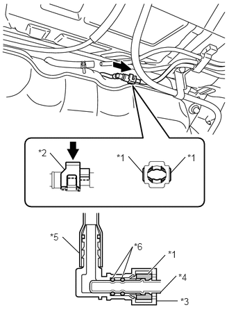
| *1 | Retainer |
| *2 | Fuel Tube Connector Cover |
| *3 | Fuel Tube Connector |
| *4 | Fuel Pipe |
| *5 | Nylon Tube |
| *6 | O-ring |

|
Push |
Line up the fuel main tube and fuel tube connector, and push them together until a "click" sound is heard. If the fuel main tube is difficult to push into the fuel tube connector, apply a small amount of clean engine oil to the tip of the fuel main tube and reinsert it.
Engage the lock of the fuel tube connector cover.
- NOTICE:
- ·
Check that there is no damage or foreign matter around the connecting parts of the fuel tube connector and fuel main tube before starting this step.
·After connecting the fuel tube connector, check that it is securely connected by pulling on it.
77028F
9.CONNECT NO. 2 FUEL EMISSION TUBE SUB-ASSEMBLY
Connect the No. 2 fuel emission tube sub-assembly to the fuel tank to canister tube and slide the hose clip to secure it.
46420
10.CONNECT NO. 2 PARKING BRAKE CABLE ASSEMBLY
Connect the No. 2 parking brake cable assembly to the vehicle with the 2 bolts.
- Torque:
- 6.0 N*m (61 kgf*cm, 53 in.*lbf)
77641A
11.INSTALL NO. 1 FUEL TANK PROTECTOR
Install the No. 1 fuel tank protector to the vehicle with the bolt and clip.
- Torque:
- 5.4 N*m (55 kgf*cm, 48 in.*lbf)
58156
12.INSTALL FRONT NO. 4 FLOOR HEAT INSULATOR
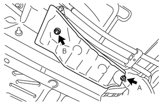
Install the front No. 4 floor heat insulator to the vehicle with the 2 nuts.
- Torque:
- Nut A : 5.4 N*m (55 kgf*cm, 48 in.*lbf)
- Nut B : 5.5 N*m (56 kgf*cm, 49 in.*lbf)
17410
13.INSTALL FRONT EXHAUST PIPE ASSEMBLY
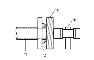
| *1 | Exhaust Manifold Converter Sub-assembly |
| *2 | Exhaust Pipe Gasket |
| *a | Wooden Block |
| *b | Plastic Hammer |
Using a plastic hammer and a wooden block, tap in a new exhaust pipe gasket until its surface is flush with the exhaust manifold converter sub-assembly.
- NOTICE:
- ·
Install the exhaust pipe gasket in the correct direction.
·Do not reuse the exhaust pipe gasket.
·Do not damage the exhaust pipe gasket by dropping it, etc.
·Do not damage the outer surface of the exhaust pipe gasket.
·Do not push in the exhaust pipe gasket with the front exhaust pipe assembly when connecting it.
w/ Compression Spring:
| *1 | Front Exhaust Pipe Assembly |
| *2 | Exhaust Pipe Gasket |
| *a | Wooden Block |
| *b | Plastic Hammer |
Using a plastic hammer and a wooden block, tap in a new exhaust pipe gasket until its surface is flush with the front exhaust pipe assembly.
- NOTICE:
- ·
Install the exhaust pipe gasket in the correct direction.
·Do not reuse the exhaust pipe gasket.
·Do not damage the exhaust pipe gasket by dropping it, etc.
·Do not damage the outer surface of the exhaust pipe gasket.
·Do not push in the exhaust pipe gasket with the front exhaust pipe assembly when connecting it.
w/o Compression Spring:
Install a new exhaust pipe gasket to the front exhaust pipe sub-assembly.
Connect the 3 exhaust pipe supports to install the front exhaust pipe assembly to the vehicle.
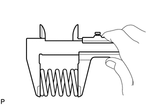
Using a vernier caliper, measure the free length of the compression spring.
- Free Length of Compression Spring:
Standard Length Minimum Length 42 mm (1.65 in.) 40.5 mm (1.59 in.)
If the length is not as specified, replace the compression spring.
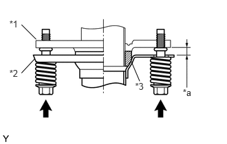
| *1 | Exhaust Manifold Converter Sub-assembly |
| *2 | Front Exhaust Pipe Assembly |
| *3 | Exhaust Pipe Gasket |
| *a | Space between flanges: 8.5 mm (0.335 in.) |
Connect the front exhaust pipe sub-assembly to the exhaust manifold converter sub-assembly with the 2 compression springs and 2 bolts.
- Torque:
43 N*m (440 kgf*cm, 32 ft.*lbf)
- NOTICE:
-
After the installation, check that the gaps between the flanges of the exhaust manifold converter sub-assembly and front exhaust pipe assembly are consistent front-to-rear and left-to-right.
w/ Compression Spring:
Using a vernier caliper, measure the free length of the compression spring.
- Free Length of Compression Spring:
Standard Length Minimum Length 40 mm (1.57 in.) 38.5 mm (1.52 in.)
If the length is not as specified, replace the compression spring.
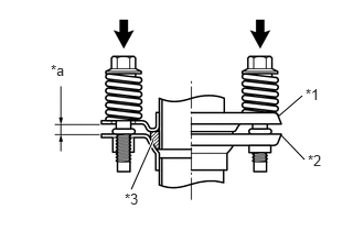
| *1 | Front Exhaust Pipe Assembly |
| *2 | Tail Exhaust Pipe Assembly |
| *3 | Exhaust Pipe Gasket |
| *a | Space between flanges: 6.5 mm (0.256 in.) |
Connect the front exhaust pipe assembly to the tail exhaust pipe assembly with the 2 compression springs and 2 bolts.
- Torque:
43 N*m (440 kgf*cm, 32 ft.*lbf)
- NOTICE:
-
After the installation, check that the gaps between the flanges of the tail exhaust pipe assembly and front exhaust pipe assembly are consistent front-to-rear and left-to-right.
w/o Compression Spring:
Connect the front exhaust pipe assembly to the tail exhaust pipe assembly with the 2 bolts.
- Torque:
- 19 N*m (194 kgf*cm, 14 ft.*lbf)
Engage the clamp to connect the heated oxygen sensor wire to the wire harness clamp bracket.
Connect the heated oxygen sensor connector.
57533B
14.INSTALL FRONT FLOOR CENTER BRACE
15.INSTALL REAR WHEEL LH
- Torque:
- 103 N*m (1050 kgf*cm, 76 ft.*lbf)
16.INSTALL FUEL SUCTION TUBE WITH PUMP AND GAUGE ASSEMBLY
17.ADD FUEL
18.INSPECT FOR FUEL LEAK
19.INSPECT FOR EXHAUST GAS LEAK
- HINT:
-
Perform "Inspection After Repairs" after repairing or replacing the exhaust system.
-
Click hereEngine / Hybrid System>1NR-FE ENGINE CONTROL>SFI SYSTEM>INITIALIZATION