POWER ASSIST SYSTEMS POWER STEERING SYSTEM(for TMMIN Made) Power Steering Warning Light Circuit
DESCRIPTION
If the power steering ECU assembly detects a malfunction, the power steering warning light comes on. At this time, the power steering ECU assembly stores a DTC in its memory.
When the power supply voltage to the power steering ECU assembly (terminal IG) drops, the required steering effort increases and the power steering warning light turns on.
WIRING DIAGRAM
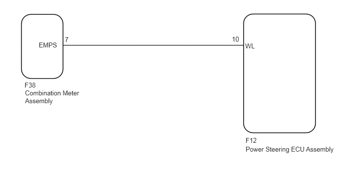
CAUTION / NOTICE / HINT
- NOTICE:
-
If the power steering ECU assembly, electric power steering column sub-assembly or power steering motor assembly have been replaced, perform torque sensor zero point calibration.
-
Click hereSteering>POWER ASSIST SYSTEMS>POWER STEERING SYSTEM(for TMMIN Made)>CALIBRATION
- HINT:
-
This flowchart is the inspection method for use when the power steering warning light remains on.
PROCEDURE
Disconnect the F12 power steering ECU assembly connector.
Disconnect the F38 combination meter assembly connector.
Measure the resistance according to the value(s) in the table below.
- Standard Resistance:
Tester Connection Condition Specified Condition F12-10 (WL) - F38-7 (EMPS) Always Below 1 Ω F12-10 (WL) or F38-7 (EMPS) - Body ground Always 10 kΩ or higher
- Result:
Proceed to OK NG
OK
NG
Disconnect the F12 power steering ECU assembly connector.
Turn the ignition switch to ON and check the condition of the power steering warning light illumination.
- OK:
After turning the ignition switch to ON, the power steering warning light illuminates.
- Result:
Proceed to OK NG
OK
NG