Home › Vehicle Interior › HEATING / AIR CONDITIONING › AIR CONDITIONING SYSTEM(for Manual Air Conditioning System) › from 2017.10
RM30M0E _58 Vehicle Interior _017118 HEATING / AIR CONDITIONING _0086991 AIR CONDITIONING SYSTEM(for Manual Air Conditioning System) J

HEATING / AIR CONDITIONING  AIR CONDITIONING SYSTEM(for Manual Air Conditioning System)  Recirculation Damper Servo Motor Circuit  


DESCRIPTION

The recirculation damper servo sub-assembly is powered through the ECU-IG NO. 1 fuse. Operating the heater control and accessory assembly drives the recirculation damper servo sub-assembly to switch between "FRESH" and "RECIRCULATION".

WIRING DIAGRAM
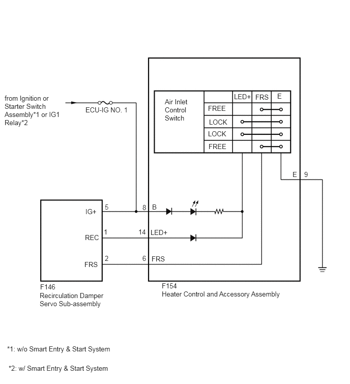
E371822E07
1.75,2.167 3.583,2.365 1.833,0.198 10 false ECU-IG NO. 1 0.094,1.927 1.302,2.802 1.208,0.875 10 false from Ignition or Starter Switch Assembly*1 or IG1 Relay*2 0.813,5.969 2.177,6.594 1.365,0.625 10 false Recirculation Damper Servo Sub-assembly 0.823,5.792 1.49,6.125 0.667,0.333 10 false F146 3.313,5.938 6.063,6.354 2.75,0.417 10 false Heater Control and Accessory Assembly 3.313,5.771 3.979,6.104 0.667,0.333 10 false F154 3.375,2 3.896,2.917 0.521,0.917 10 false Air Inlet Control Switch 4.26,2.135 4.927,2.417 0.667,0.281 10 false FREE 4.281,2.417 4.948,2.698 0.667,0.281 10 false LOCK 4.26,2.656 4.927,2.938 0.667,0.281 10 false LOCK 4.271,2.917 4.938,3.198 0.667,0.281 10 false FREE 5.229,1.906 5.896,2.188 0.667,0.281 10 false FRS 4.792,1.896 5.458,2.177 0.667,0.281 10 false LED+ 5.677,1.885 6.344,2.167 0.667,0.281 10 false E 5.99,3.49 6.656,3.771 0.667,0.281 10 false E 2.917,5.208 3.25,5.542 0.333,0.333 10 false 6 1.729,5.333 2.396,5.615 0.667,0.281 10 false FRS 2.833,4.667 3.167,5 0.333,0.333 10 false 14 3.083,4.677 3.75,4.958 0.667,0.281 10 false LED+ 3.115,4.156 3.781,4.438 0.667,0.281 10 false B 2.917,4.167 3.25,4.5 0.333,0.333 10 false 8 1.75,4.25 2.417,4.531 0.667,0.281 10 false IG+ 2.146,4.156 2.479,4.49 0.333,0.333 10 false 5 2.146,5.208 2.479,5.542 0.333,0.333 10 false 2 1.74,4.781 2.406,5.063 0.667,0.281 10 false REC 2.125,4.667 2.458,5 0.333,0.333 10 false 1 3.104,5.219 3.771,5.5 0.667,0.281 10 false FRS 6.229,3.49 6.563,3.823 0.333,0.333 10 false 9 0.146,7.063 2.896,7.479 2.75,0.417 10 false *1: w/o Smart Entry & Start System 0.177,7.458 2.938,7.781 2.76,0.323 10 false *2: w/ Smart Entry & Start System

CAUTION / NOTICE / HINT

NOTICE:

Inspect the fuses for circuits related to this system before performing the following inspection procedures.


PROCEDURE

1.INSPECT RECIRCULATION DAMPER SERVO SUB-ASSEMBLY

OK

2.CHECK HARNESS AND CONNECTOR (RECIRCULATION DAMPER SERVO SUB-ASSEMBLY - POWER SOURCE)

NG

2.CHECK HARNESS AND CONNECTOR (RECIRCULATION DAMPER SERVO SUB-ASSEMBLY - POWER SOURCE)
a.

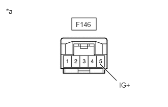
Disconnect the recirculation damper servo sub-assembly connector.

b.
E371823C05
1.469,0.365 1.969,0.615 0.5,0.25 2.052,1.313 2.385,1.646 true 2.438,1.656 2.75,1.854 0.313,0.198 10 false IG+ 0.125,0.146 0.438,0.344 0.313,0.198 10 false *a 1.552,0.417 1.948,0.635 0.396,0.219 10 false F146
*a Front view of wire harness connector
(to Recirculation Damper Servo Sub-assembly)


Measure the voltage according to the value(s) in the table below.

Standard Voltage:
Tester Connection Switch Condition Specified Condition
F146-5 (IG+) -Body ground Ignition switch off Below 1 V
F146-5 (IG+) -Body ground Ignition switch ON 11 to 14 V


Result:
Result
OK
NG


OK

3.CHECK HARNESS AND CONNECTOR (HEATER CONTROL AND ACCESSORY ASSEMBLY - POWER SOURCE)

NG

REPAIR OR REPLACE HARNESS OR CONNECTOR

3.CHECK HARNESS AND CONNECTOR (HEATER CONTROL AND ACCESSORY ASSEMBLY - POWER SOURCE)
a.

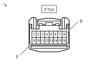
Disconnect the heater control and accessory assembly connector.

b.
E371824C06
1.406,0.177 1.906,0.427 0.5,0.25 2.208,1.146 2.625,0.729 true 0.688,1.844 1.104,1.427 true 0.104,0.083 0.417,0.281 0.313,0.198 10 false *a 1.5,0.24 1.958,0.479 0.458,0.24 10 false F154 2.688,0.625 3,0.823 0.313,0.198 10 false B 0.542,1.823 0.854,2.021 0.313,0.198 10 false E
*a Front view of wire harness connector
(to Heater Control and Accessory Assembly)


Measure the voltage and resistance according to the value(s) in the table below.

Standard Voltage:
Tester Connection Switch Condition Specified Condition
F154-8 (B) - F154-9 (E) Ignition switch off Below 1 V
F154-8 (B) - F154-9 (E) Ignition switch ON 11 to 14 V


Result:
Result
OK
NG


OK

4.CHECK HARNESS AND CONNECTOR (RECIRCULATION DAMPER SERVO SUB-ASSEMBLY - HEATER CONTROL AND ACCESSORY ASSEMBLY)

NG

REPAIR OR REPLACE HARNESS OR CONNECTOR

4.CHECK HARNESS AND CONNECTOR (RECIRCULATION DAMPER SERVO SUB-ASSEMBLY - HEATER CONTROL AND ACCESSORY ASSEMBLY)
a.

Disconnect the F146 recirculation damper servo sub-assembly connector.


b.

Disconnect the F154 heater control and accessory assembly connector.


c.

Measure the resistance according to the value(s) in the table below.

Standard Resistance:
Tester Connection Switch Condition Specified Condition
F146-5 (IG+) - F154-8 (B) Always Below 1 Ω
F146-1 (REC) - F154-14 (LED+) Always Below 1 Ω
F146-2 (FRS) - F154-6 (FRS) Always Below 1 Ω
F146-5 (IG+) or F154-8 (B) - Body ground Always 10 kΩ or higher
F146-1 (REC) or F154-14 (LED+) - Body ground Always 10 kΩ or higher
F146-2 (FRS) or F154-6 (FRS) - Body ground Always 10 kΩ or higher


Result:
Result
OK
NG


OK

NG

REPAIR OR REPLACE HARNESS OR CONNECTOR