1NR-FE EMISSION CONTROL CANISTER INSTALLATION
PROCEDURE

 77169A
1.INSTALL FUEL SUCTION TUBE SET GASKET
Apply gasoline to a new fuel suction tube set gasket and install it to the fuel tank assembly.
77020A
2.INSTALL FUEL SUCTION TUBE WITH PUMP AND GAUGE ASSEMBLY
Pass the float of the fuel suction tube with pump and gauge assembly into the fuel tank assembly.
Bend up the tip of the fuel pump filter and set the fuel suction tube with pump and gauge assembly on the fuel tank assembly.
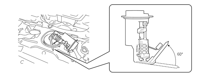
- NOTICE:
-
Be careful not to bend the arm of the fuel sender gauge assembly.
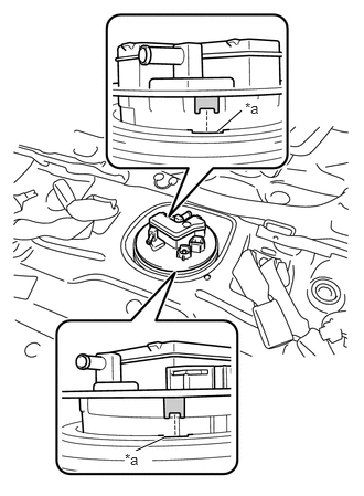
| *a | Groove |

|
Tab |
Align the 2 tabs of the fuel suction tube with pump and gauge assembly with the 2 grooves of the fuel tank assembly.
3.INSTALL FUEL PUMP GAUGE RETAINER
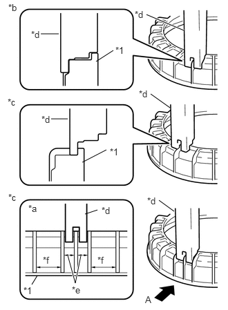
| *1 | Fuel Pump Gauge Retainer |
| *a | View A |
| *b | Correct |
| *c | Incorrect |
| *d | SST (Claw) |
| *e | Narrow |
| *f | Wide |
Temporarily install SST (plate) and SST (claw) to a new fuel pump gauge retainer.
- SST
- 09808-14030 (09808-01030, 09808-01040, 09808-01050)
- NOTICE:
- ·
Install SST (claw) to the correct location.
·Do not install SST (claw) to a location where the pitch between ribs of the fuel pump gauge retainer is narrow.
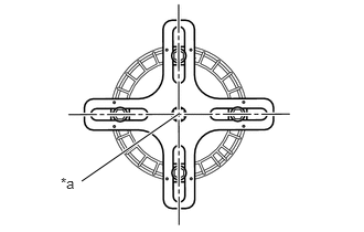
| *a | Center Point of Fuel Pump Gauge Retainer |
Adjust the position of SST (claw) so that the hole in SST (plate) for installing SST (handle) is in the center of the fuel pump gauge retainer.
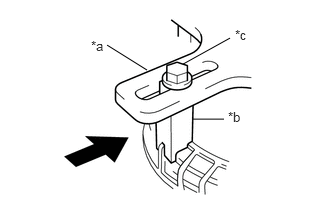
| *a | SST (Plate) |
| *b | SST (Claw) |
| *c | SST (Bolt) |

|
Press |
Press SST (claw) against the rib of the fuel pump gauge retainer and tighten SST (bolt).
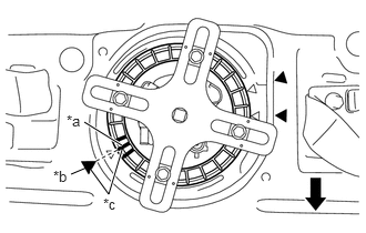
| *a | Fuel Pump Gauge Retainer Start of Threads Location |
| *b | Start of Threads Mark Copied to Vehicle Floor |
| *c | Align |
|
|
Front Side of Vehicle |
Align the start of threads mark on the fuel pump gauge retainer with the start of threads mark that was copied to the vehicle floor as shown in the illustration.
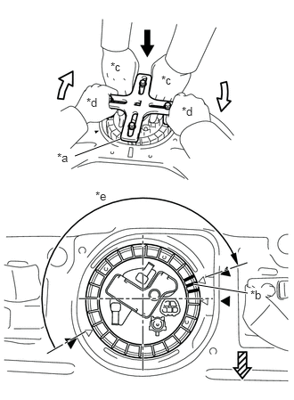
| *a | SST (Plate) |
| *b | Fuel Pump Gauge Retainer Start of Threads Location |
| *c | Worker A |
| *d | Worker B |
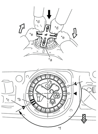
| *e | Approximately 180° |
|
|
Press Down |

|
Slowly Rotate |

|
Front Side of Vehicle |
While one person presses down to prevent the fuel pump gauge retainer and fuel suction tube with pump and gauge assembly from rotating together, the other person should firmly press the fuel pump gauge retainer against the threads of the fuel tank assembly, and tighten it by rotating it approximately 180°.
- CAUTION:
-
Make sure not to pinch your hands with SST.
- NOTICE:
- ·
Be careful not to apply excessive downward force to SST, as this may damage the fuel suction tube with pump and gauge assembly or fuel tank assembly.
·Turning SST at an angle may cause it to slip off of the fuel pump gauge retainer, so be sure SST is horizontal when turning.
·To prevent damage to parts, do not turn SST too vigorously.
·If SST slips off of the fuel pump gauge retainer, loosen SST (bolt) and install SST again.
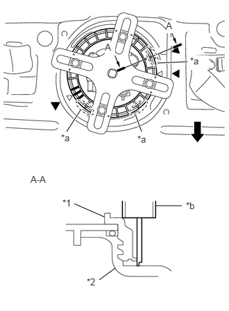
As shown in the illustration, quickly and firmly press down on the part of the fuel pump gauge retainer closest to the front side of the vehicle so that it no longer rises up.
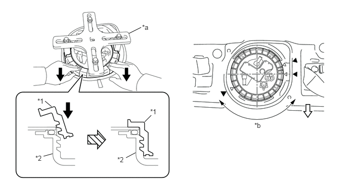
| *1 | Fuel Pump Gauge Retainer | *2 | Fuel Tank Assembly |
| *a | SST (Plate) | *b | Fuel Pump Gauge Retainer Rising Up |
|
|
Press Quickly and Firmly |
|
Front Side of Vehicle |
- HINT:
- ·
If the fuel pump gauge retainer cannot be properly pressed down due to the position of SST, set SST in a different position.
·When pressing down the fuel pump gauge retainer, there will be a sound or tactile sensation of parts contacting and pressing together when the fuel pump gauge retainer is fully pressed down, and at this point it will stop rising up.
| *a | SST (Plate) |
| *b | Fuel Pump Gauge Retainer Start of Threads Location |
| *c | Copied Start of Threads Mark |
| *d | Worker A |
| *e | Worker B |
| *f | Rotate to Start of Threads Mark on Vehicle Floor |
|
|
Press Down |
|
|
Slowly Rotate |
|
|
Front Side of Vehicle |
While one person presses down to prevent the fuel pump gauge retainer and fuel suction tube with pump and gauge assembly from rotating together, the other person should slowly rotate SST (plate) and tighten the fuel pump gauge retainer until it reaches the start of threads mark that was copied to the vehicle floor.
- CAUTION:
-
Make sure not to pinch your hands with SST.
| *1 | Fuel Pump Gauge Retainer |
| *2 | Fuel Tank Assembly |
| *a | Measurement Location |
| *b | Vernier Caliper |
|
|
Front Side of Vehicle |
Check the tightening condition of the fuel pump gauge retainer.
Using a vernier caliper, measure the upper surface of the fuel tank assembly in the 3 locations shown in the illustration.
- Specification:
Difference between the 3 measured values is within 3 mm (0.118 in.).
- NOTICE:
-
If the difference between measurements is approximately 6 mm (0.236 in.), the threads are cross-threaded by one row (6 mm (0.236 in.)), so remove and reinstall the fuel pump gauge retainer.
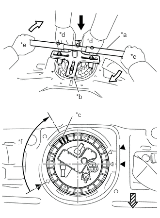
| *a | SST (Handle) |
| *b | SST (Plate) |
| *c | Fuel Pump Gauge Retainer Start of Threads Location |
| *d | Worker A |
| *e | Worker B |
| *f | Approximately 90° |
|
|
Press Down |
|
|
Slowly Rotate |
|
|
Front Side of Vehicle |
Install SST (handle) to SST (plate).
- SST
- 09808-14030 (09808-01010, 09808-01020, 09808-01030, 09808-01040, 09808-01050)
While one person presses down to prevent the fuel pump gauge retainer and fuel suction tube with pump and gauge assembly from rotating together, the other person should slowly rotate SST (handle) and tighten the fuel pump gauge retainer by approximately 90°.
- CAUTION:
-
Make sure not to pinch your hands with SST.
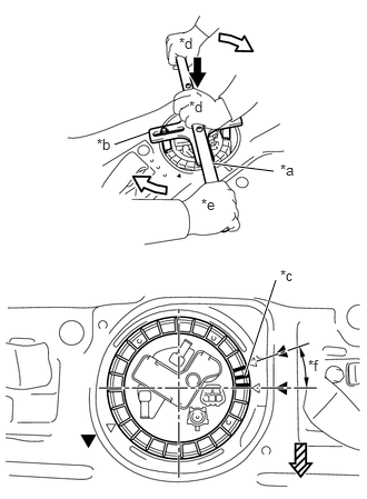
| *a | SST (Handle) |
| *b | SST (Plate) |
| *c | Fuel Pump Gauge Retainer Start of Threads Location |
| *d | Worker A |
| *e | Worker B |
| *f | Fully Tightened Position |
|
|
Hold Down |
|
|
Slowly Rotate |
|
|
Front Side of Vehicle |
To make sure SST does not separate from the fuel pump gauge retainer, one person should hold down the center of SST from above while at the same time both people slowly rotate SST (handle), and slowly tighten the fuel pump gauge retainer until it reaches the fully tightened position.
77209F
4.CONNECT FUEL TANK MAIN TUBE SUB-ASSEMBLY
Connect the fuel tank main tube sub-assembly to the fuel suction tube with pump and gauge assembly.
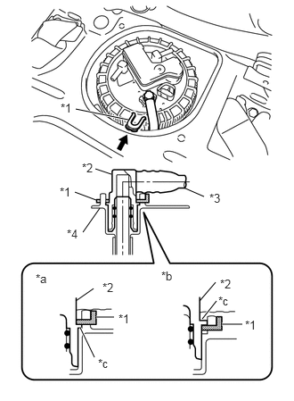
| *1 | Tube Joint Clip |
| *2 | Fuel Tube Joint |
| *3 | Nylon Tube |
| *4 | Fuel Suction Plate |
| *a | Correct |
| *b | Incorrect |
| *c | Rib |
Install the tube joint clip.
- NOTICE:
- ·
Make sure there is no damage to or foreign matter on the connecting surfaces.
·Check that the fuel tube joint is correctly and fully inserted.
·Check that the tube joint clip is above the rib of the fuel tube joint.
·After installing the tube joint clip, make sure the fuel tube joint is secure.
·Do not damage any of the clips. If a tube joint clip is damaged, replace it.
5. CHECK AIRTIGHTNESS
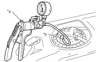
| *a | Vacuum Pump |
| *b | Port B |
Install a vacuum pump to port B of the fuel suction tube with pump and gauge assembly as shown in the illustration.
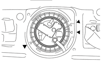
|
|
Apply Soapy Water Here |
Apply soapy water to the contact areas between the fuel suction tube with pump and gauge assembly and the fuel pump gauge retainer.
- NOTICE:
-
Cover the connecters of the fuel suction tube with pump and gauge assembly with protective tape.
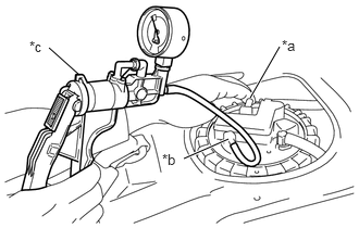
| *a | Port A |
| *b | Port B |
| *c | Vacuum Pump |
Close port A and use the vacuum pump to apply 5 kPa (0.1 kgf/cm2, 1 psi) of compressed air to port B as shown in the illustration.
- NOTICE:
-
Do not apply more compressed air than necessary.
Check that the contact areas between the fuel suction tube with pump and gauge assembly and fuel pump gauge retainer are airtight.
- NOTICE:
- ·
If air bubbles appear, remove and reinstall the fuel pump gauge retainer.
·After a fuel pump gauge retainer and fuel suction tube set gasket have been used once, replace them with new parts.
·When removing and reinstalling the fuel pump gauge retainer, make sure to clean away the soapy water to prevent the fuel suction tube set gasket from slipping out of position and being assembled incorrectly.
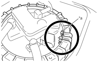
- HINT:
-
 2.188,1.104 2.75,0.656 true 2.76,0.552 3.073,0.708 0.313,0.156 10 false *a
*a Air Bubbles
-
If the assembled components are not airtight due to improper installation of the fuel pump gauge retainer, etc., air bubbles will appear as shown in the illustration.
77701W
6.CONNECT NO. 1 CANISTER OUTLET HOSE SUB-ASSEMBLY
Connect the No. 1 canister outlet hose sub-assembly to the fuel suction tube with pump and gauge assembly.
77028F
7.CONNECT NO. 2 FUEL EMISSION TUBE SUB-ASSEMBLY
Connect the No. 2 fuel emission tube sub-assembly to the fuel suction tube with pump and gauge assembly and slide the hose clip to secure it.
8.INSPECT FOR FUEL LEAK
58325E
9.INSTALL REAR FLOOR SERVICE HOLE COVER
Fully remove any butyl tape remaining on the rear floor service hole cover and vehicle floor.
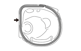
|
|
Butyl Tape |
Apply a new butyl tape to the rear floor service hole cover as shown in the illustration.
Connect the fuel suction tube with pump and gauge assembly connector.
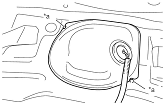
| *a | Alignment Mark |
Align the 2 alignment marks, and install the rear floor service hole cover to the vehicle floor.
for TMMIN Made:
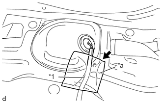
| *1 | Fuel Suction Tube with Pump and Gauge Assembly Wire |
| *a | Bead of the Vehicle Floor |
Install a new wiring harness protector to the rear floor service hole cover and vehicle floor.
- NOTICE:
-
Make sure the fuel suction tube with pump and gauge assembly wire is aligned with the tip of the bead of the vehicle floor.
for TMT Made:
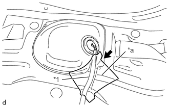
| *1 | Fuel Suction Tube with Pump and Gauge Assembly Wire |
| *a | Bead of the Vehicle Floor |
Install a new wiring harness protector to the rear floor service hole cover and vehicle floor.
- NOTICE:
-
Make sure the fuel suction tube with pump and gauge assembly wire is aligned with the tip of the bead of the vehicle floor.
73707
10.INSTALL CHILD RESTRAINT SEAT ANCHOR INNER BRACKET SUB-ASSEMBLY