2NR-FE ENGINE MECHANICAL ENGINE UNIT INSTALLATION
CAUTION / NOTICE / HINT
- HINT:
-
Perform "Inspection After Repair" after replacing the ignition coil assembly or fuel injector assembly.
-
Click hereEngine / Hybrid System>2NR-FE ENGINE CONTROL>SFI SYSTEM>INITIALIZATION
PROCEDURE

 1.INSTALL WIRE HARNESS CLAMP BRACKET
Install the wire harness clamp bracket to the cylinder block sub-assembly with the bolt.
- Torque:
- 12.8 N*m (131 kgf*cm, 9 ft.*lbf)
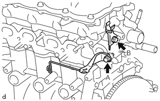
Install the 2 wire harness clamp brackets to the cylinder head sub-assembly with the 2 bolts.
- Torque:
- Bolt A (for TMMIN Made) : 29 N*m (296 kgf*cm, 21 ft.*lbf)
- Bolt A (for TMT Made) : 30 N*m (306 kgf*cm, 22 ft.*lbf)
- Bolt B : 8.4 N*m (86 kgf*cm, 74 in.*lbf)
Install the wire harness clamp bracket to the cylinder head cover sub-assembly with the bolt.
- Torque:
- 8.4 N*m (86 kgf*cm, 74 in.*lbf)
16620
2.INSTALL V-RIBBED BELT TENSIONER ASSEMBLY
Install the V-ribbed belt tensioner assembly to the timing chain cover assembly with the 2 bolts.
- Torque:
- 21 N*m (214 kgf*cm, 15 ft.*lbf)
16268
3.INSTALL NO. 1 WATER BY-PASS PIPE
Connect the No. 1 water by-pass hose to the water inlet with thermostat sub-assembly and slide the hose clip to secure it.
Install the No. 1 water by-pass pipe to the cylinder block sub-assembly with the bolt.
- Torque:
- 22 N*m (224 kgf*cm, 16 ft.*lbf)
Engage the clamp to connect the water by-pass hose to the hose clamp.
4.INSTALL NO. 2 VENTILATION HOSE
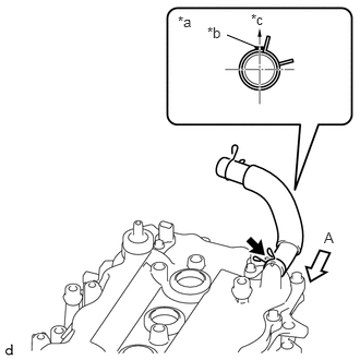
| *a | View A |
| *b | Paint Mark |
| *c | Top of Engine |
Install the No. 2 ventilation hose to the cylinder head cover sub-assembly and slide the hose clip to secure it.
- NOTICE:
-
Perform the installation with the No. 2 ventilation hose and hose clip at the correct angle.
19500D
5.INSTALL NO. 1 IGNITION COIL
6.INSTALL INTAKE MANIFOLD WITH THROTTLE BODY WITH MOTOR ASSEMBLY
Install a new No. 1 intake manifold to head gasket to the intake manifold.
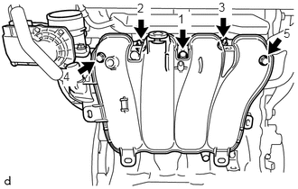
Temporarily install the intake manifold with the throttle body with motor assembly to the cylinder head sub-assembly with the 3 bolts and 2 nuts.
- NOTICE:
-
Make sure there is no oil adhering to the bolts or threaded holes.
Fully tighten the 3 bolts and 2 nuts, in the sequence shown in the illustration.
- Torque:
- 28 N*m (286 kgf*cm, 21 ft.*lbf)
16264
7.CONNECT NO. 2 WATER BY-PASS HOSE
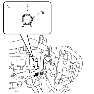
| *a | View A |
| *b | Paint Mark |
| *c | Front of Engine |
Connect the No. 2 water by-pass hose to the cylinder head sub-assembly and slide the hose clip to secure it.
- NOTICE:
-
Perform the installation with the No. 2 water by-pass hose and hose clip at the correct angle.
16267
8.CONNECT NO. 3 WATER BY-PASS HOSE
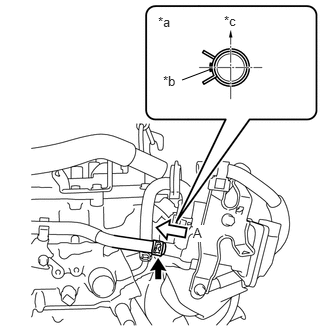
| *a | View A |
| *b | Paint Mark |
| *c | Top of Engine |
Connect the No. 3 water by-pass hose to the throttle body with motor assembly and slide the hose clip to secure it.
- NOTICE:
-
Perform the installation with the No. 3 water by-pass hose and hose clip at the correct angle.
12261
9.INSTALL VENTILATION HOSE
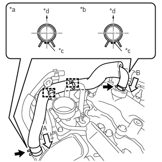
| *a | View A |
| *b | View B |
| *c | Paint Mark |
| *d | Exhaust Side |
Install the ventilation hose to the cylinder head cover sub-assembly and intake manifold and slide the 2 hose clips to secure them.
- NOTICE:
-
Perform the installation with the ventilation hose and hose clip at the correct angle.
Engage the 2 clamps to connect the ventilation hose to the hose clamp.
10.INSTALL FUEL INJECTOR ASSEMBLY
23891
11.INSTALL FUEL DELIVERY SPACER
23814B
12.INSTALL FUEL DELIVERY PIPE
25051
13.INSTALL EXHAUST MANIFOLD CONVERTER SUB-ASSEMBLY
17118
14.INSTALL MANIFOLD STAY