Home › Audio / Visual / Telematics › AUDIO / VIDEO › AUDIO & VISUAL SYSTEM › 2017.10–2018.01
RM30M0E _56 Audio / Visual / Telematics _017106 AUDIO / VIDEO _0084785 AUDIO & VISUAL SYSTEM J

AUDIO / VIDEO  AUDIO & VISUAL SYSTEM  Illumination Circuit  


DESCRIPTION

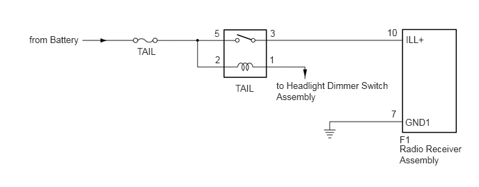
Power is supplied to the radio receiver assembly illumination when the light control switch is in the tail or head position.

WIRING DIAGRAM

for TMMIN Made
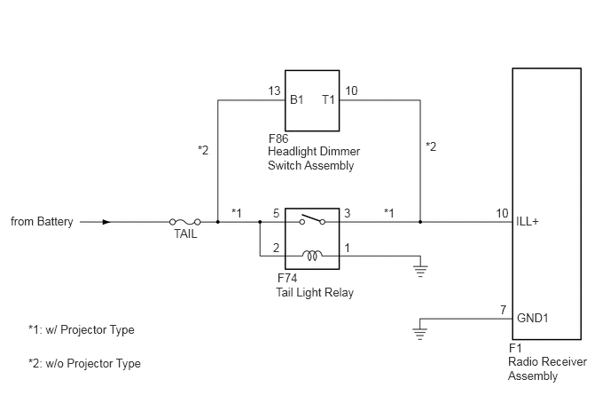

E272469E03
0.125,2.51 1.073,2.708 0.948,0.198 10 false from Battery 2.042,2.656 2.458,2.844 0.417,0.188 10 false TAIL 2.719,2.417 3,2.615 0.281,0.198 10 false *1 4.51,2.417 4.792,2.615 0.281,0.198 10 false *1 3.208,2.417 3.49,2.615 0.281,0.198 10 false 5 4.042,2.417 4.323,2.615 0.281,0.198 10 false 3 3.208,2.823 3.49,3.021 0.281,0.198 10 false 2 4.042,2.823 4.323,3.021 0.281,0.198 10 false 1 3.26,3.177 3.542,3.375 0.281,0.198 10 false F74 3.24,3.344 4.26,3.552 1.021,0.208 10 false Tail Light Relay 5.979,4 6.26,4.198 0.281,0.198 10 false F1 5.969,4.156 6.906,4.531 0.938,0.375 10 false Radio Receiver Assembly 2.323,1.677 2.604,1.875 0.281,0.198 10 false *2 5,1.635 5.281,1.833 0.281,0.198 10 false *2 4.052,0.979 4.333,1.177 0.281,0.198 10 false 10 3.146,0.979 3.427,1.177 0.281,0.198 10 false 13 3.406,1.083 3.688,1.281 0.281,0.198 10 false B1 3.781,1.083 4.063,1.281 0.281,0.198 10 false T1 3.156,1.542 3.438,1.74 0.281,0.198 10 false F86 3.146,1.688 4.292,2.052 1.146,0.365 10 false Headlight Dimmer Switch Assembly 0.333,3.781 1.708,4 1.375,0.219 10 false *1: w/ Projector Type 0.333,4.177 2.021,4.375 1.688,0.198 10 false *2: w/o Projector Type 5.823,2.417 6.104,2.615 0.281,0.198 10 false 10 6.063,2.51 6.469,2.719 0.406,0.208 10 false ILL+ 5.875,3.552 6.156,3.75 0.281,0.198 10 false 7 6.073,3.646 6.552,3.854 0.479,0.208 10 false GND1


for TMT Made


E373438E01
4.135,1.198 5.844,1.563 1.708,0.365 10 false to Headlight Dimmer Switch Assembly 5.979,2.146 6.917,2.51 0.938,0.365 10 false Radio Receiver Assembly 3.521,1.24 4.135,1.438 0.615,0.198 10 false TAIL 2.052,0.688 2.667,0.885 0.615,0.198 10 false TAIL 6.063,1.75 6.677,1.948 0.615,0.198 10 false GND1 6.073,0.51 6.688,0.708 0.615,0.198 10 false ILL+ 0.438,0.51 1.573,0.76 1.135,0.25 10 false from Battery 3.208,0.417 3.365,0.615 0.156,0.198 10 false 5 3.219,0.813 3.375,1.01 0.156,0.198 10 false 2 4.031,0.813 4.188,1.01 0.156,0.198 10 false 1 4.042,0.417 4.198,0.615 0.156,0.198 10 false 3 5.792,0.406 6.344,0.594 0.552,0.188 10 false 10 5.854,1.625 6.01,1.823 0.156,0.198 10 false 7 5.979,2.01 6.875,2.177 0.896,0.167 10 false F1


CAUTION / NOTICE / HINT

NOTICE:
·

The vehicle is equipped with a Supplemental Restraint System (SRS) which includes components such as airbags. Before servicing (including removal or installation of parts), be sure to read the precaution for Supplemental Restraint System.

Click hereVehicle Interior>SUPPLEMENTAL RESTRAINT SYSTEMS>AIRBAG SYSTEM>PRECAUTION

·

Inspect the fuses for circuits related to this system before performing the following procedure.


PROCEDURE

1.CHECK ILLUMINATION
a.

Check if the illumination for the radio receiver assembly, air conditioner control switch or others comes on when the light control switch is turned to the head or tail position.

Result:
Result Proceed to
Illumination comes on for all components except radio receiver assembly. A
No illumination comes on (radio receiver assembly, hazard switch, air conditioner control switch, etc.). B


A

2.CHECK HARNESS AND CONNECTOR (ILLUMINATION SIGNAL)

B

2.CHECK HARNESS AND CONNECTOR (ILLUMINATION SIGNAL)
a.
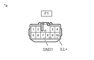
E259248C14
1.51,0.396 1.896,0.594 0.385,0.198 2.271,1.656 2.083,1.354 true 1.75,1.667 1.594,1.365 true 0.146,0.115 0.458,0.271 0.313,0.156 10 false *a 1.625,0.406 1.969,0.615 0.344,0.208 10 false F1 2.198,1.708 2.75,1.927 0.552,0.219 10 false ILL+ 1.563,1.719 2,1.917 0.438,0.198 10 false GND1
*a Front view of wire harness connector (to Radio Receiver Assembly)


Disconnect the radio receiver assembly connector.


b.

Measure the voltage according to the value(s) in the table below.

Standard Voltage:
Tester Connection Condition Specified Condition
F1-10 (ILL+) - Body ground Light control switch in the tail or head position 11 to 14 V


c.

Measure the resistance according to the value(s) in the table below.

Standard Resistance:
Tester Connection Condition Specified Condition
F1-7 (GND1) - Body ground Always Below 1 V


Result:
Result Proceed to
OK (for TMMIN Made) A
OK (for TMT Made) B
NG C


A

B

C

REPAIR OR REPLACE HARNESS OR CONNECTOR