Home › Audio / Visual / Telematics › AUDIO / VIDEO › AUDIO & VISUAL SYSTEM › from 2017.10
RM30M0E _56 Audio / Visual / Telematics _017106 AUDIO / VIDEO _0084785 AUDIO & VISUAL SYSTEM J

AUDIO / VIDEO  AUDIO & VISUAL SYSTEM  Microphone Circuit between Microphone and Radio Receiver  


DESCRIPTION

Using this circuit, the radio receiver assembly sends power to the telephone microphone assembly, and the telephone microphone assembly sends microphone signals to the radio receiver assembly.

WIRING DIAGRAM
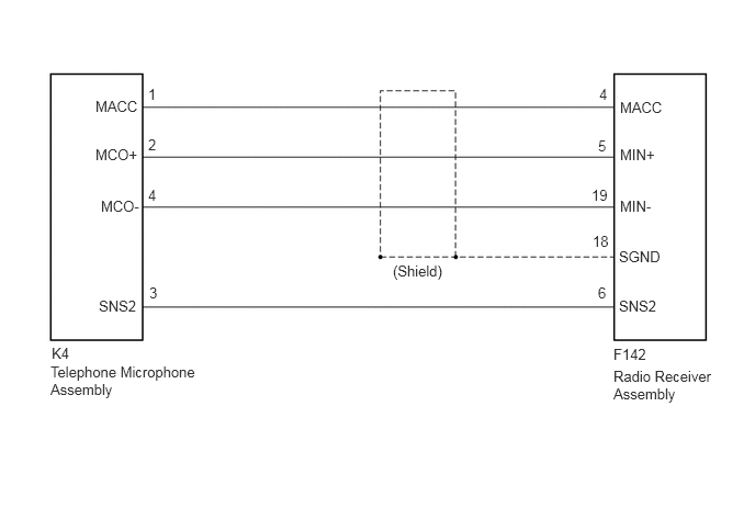
E370199E09
5.885,0.938 6.5,1.135 0.615,0.198 10 false MACC 5.885,1.385 6.5,1.583 0.615,0.198 10 false MIN+ 0.958,1.875 1.573,2.073 0.615,0.198 10 false MCO- 5.875,2.354 6.49,2.552 0.615,0.198 10 false SGND 5.875,2.823 6.49,3.021 0.615,0.198 10 false SNS2 0.938,2.823 1.552,3.021 0.615,0.198 10 false SNS2 0.906,1.385 1.521,1.583 0.615,0.198 10 false MCO+ 0.906,0.927 1.521,1.125 0.615,0.198 10 false MACC 3.729,2.49 4.438,2.792 0.708,0.302 10 false (Shield) 5.823,3.281 6.438,3.479 0.615,0.198 10 false F142 0.49,3.271 1.104,3.469 0.615,0.198 10 false K4 5.823,3.49 6.771,3.958 0.948,0.469 10 false Radio Receiver Assembly 0.479,3.448 1.844,4 1.365,0.552 10 false Telephone Microphone Assembly 5.885,1.875 6.5,2.073 0.615,0.198 10 false MIN- 1.417,2.698 1.573,2.896 0.156,0.198 10 false 3 5.688,0.813 5.844,1.01 0.156,0.198 10 false 4 1.406,0.813 1.563,1.01 0.156,0.198 10 false 1 1.406,1.292 1.563,1.49 0.156,0.198 10 false 2 1.406,1.771 1.563,1.969 0.156,0.198 10 false 4 5.677,1.302 5.833,1.5 0.156,0.198 10 false 5 5.615,1.771 6,1.969 0.385,0.198 10 false 19 5.625,2.208 6.01,2.406 0.385,0.198 10 false 18 5.677,2.698 6.063,2.896 0.385,0.198 10 false 6

PROCEDURE

1.CHECK HARNESS AND CONNECTOR (RADIO RECEIVER ASSEMBLY - TELEPHONE MICROPHONE ASSEMBLY)
a.

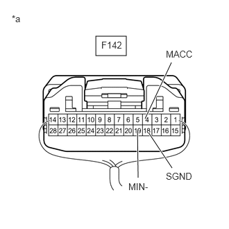
Disconnect the F142 radio receiver assembly connector.


b.

Disconnect the K4 telephone microphone assembly connector.

c.

Measure the resistance according to the value(s) in the table below.

Standard Resistance:
Tester Connection Condition Specified Condition
F142-6 (SNS2) - K4-3 (SNS2) Always Below 1 Ω
F142-4 (MACC) - K4-1 (MACC) Always Below 1 Ω
F142-5 (MIN+) - K4-2 (MCO+) Always Below 1 Ω
F142-19 (MIN-) - K4-4 (MCO-) Always Below 1 Ω
F142-6 (SNS2) or K4-3 (SNS2) - Body ground Always 10 kΩ or higher
F142-4 (MACC) or K4-1 (MACC) - Body ground Always 10 kΩ or higher
F142-5 (MIN+) or K4-2 (MCO+) - Body ground Always 10 kΩ or higher
F142-19 (MIN-) or K4-4 (MCO-) - Body ground Always 10 kΩ or higher
F142-18 (SGND) - Body ground Always 10 kΩ or higher


Result:
Proceed to
OK
NG


OK

2.INSPECT RADIO RECEIVER ASSEMBLY

NG

REPAIR OR REPLACE HARNESS OR CONNECTOR

2.INSPECT RADIO RECEIVER ASSEMBLY
a.

Reconnect the radio receiver assembly connector.


b.

Reconnect the K4 telephone microphone assembly connector.

c.
E370196C06
1.438,0.542 1.896,0.833 0.458,0.292 2.073,2.667 2.063,1.958 true 2.573,0.938 2.177,1.781 true 2.583,2.521 2.229,1.99 true 0.177,0.198 0.49,0.396 0.313,0.198 10 false *a 2.49,0.729 3.031,1.052 0.542,0.323 10 false MACC 2.49,2.563 3.031,2.885 0.542,0.323 10 false SGND 1.927,2.719 2.469,3.042 0.542,0.323 10 false MIN- 1.521,0.594 2.031,0.885 0.51,0.292 10 false F142
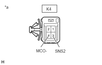
*a Component with harness connected
(Radio Receiver Assembly)


Measure the voltage according to the value(s) in the table below.

Standard Voltage:
Tester Connection Condition Specified Condition
F142-4 (MACC) - Body ground Ignition switch ACC 4 to 6 V


d.

Measure the resistance according to the value(s) in the table below.

Standard Resistance:
Tester Connection Condition Specified Condition
F142-18 (SGND) - Body ground Always Below 1 Ω
F142-19 (MIN-) - Body ground Always Below 1 Ω


Result:
Proceed to
OK
NG


OK

3.INSPECT TELEPHONE MICROPHONE ASSEMBLY

NG

3.INSPECT TELEPHONE MICROPHONE ASSEMBLY
a.

Disconnect the telephone microphone assembly connector.


b.
E221776C31
1.417,0.167 1.917,0.417 0.5,0.25 1.375,1.583 1.625,1.229 true 2,1.583 1.792,1.24 true 0.156,0.156 0.469,0.354 0.313,0.198 10 false *a 1.219,1.625 1.625,1.823 0.406,0.198 10 false MCO- 1.854,1.635 2.26,1.833 0.406,0.198 10 false SNS2 1.563,0.219 1.969,0.417 0.406,0.198 10 false K4
*a Component without harness connected
(Telephone Microphone Assembly)


Measure the resistance according to the value(s) in the table below.

Standard Resistance:
Tester Connection Condition Specified Condition
K4-4 (MCO-) - K4-3 (SNS2) Always Below 1 Ω


Result:
Proceed to
OK
NG


OK

4.INSPECT TELEPHONE MICROPHONE ASSEMBLY

NG

REPLACE TELEPHONE MICROPHONE ASSEMBLY

4.INSPECT TELEPHONE MICROPHONE ASSEMBLY
a.

Reconnect the F142 radio receiver assembly connector.

b.
E279075C16
1.302,1 1.719,1.25 0.417,0.25 1.625,2.021 2.083,1.333 true 1.625,2.396 2,2.75 true 0.135,0.135 0.448,0.333 0.313,0.198 10 false *a 1.406,1.031 1.719,1.229 0.313,0.198 10 false K4 2.063,1.146 2.563,1.344 0.5,0.198 10 false MCO+ 2.031,2.76 2.531,2.958 0.5,0.198 10 false MCO-
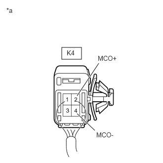
*a Component with harness connected
(Telephone Microphone Assembly)


Reconnect the telephone microphone assembly connector.


c.

Turn the ignition switch to ACC.


d.

Connect an oscilloscope to terminals 2 (MCO+) and 4 (MCO-) of the telephone microphone assembly connector.


e.

Check the waveform of the telephone microphone assembly using the oscilloscope.

Result:
Result Proceed to
A waveform synchronized with the voice input to the telephone microphone assembly is output. A
A waveform synchronized with the voice input to the telephone microphone assembly is not output. B


A

PROCEED TO NEXT SUSPECTED AREA SHOWN IN PROBLEM SYMPTOMS TABLE

B

REPLACE TELEPHONE MICROPHONE ASSEMBLY