POWER DISTRIBUTION MAIN BODY ECU(for TMT Made) INSTALLATION
PROCEDURE

 89221B
1.INSTALL BODY COMPUTER
- NOTICE:
- ·
Make sure that there is no foreign matter on the contact surfaces or connectors.
·Make sure that there is no contamination by foreign matter.
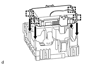
Vertically align the 4 guides on the driver side junction block assembly side with those on the body computer side.
While following the guides, slide the body computer vertically in the direction indicated by the arrow.
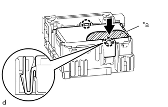
| *a | Push area |
Press the push area of the body computer with the palm of one hand to engage the body computer lock and driver side junction block assembly lock.
When the 2 claws of the locks engage, check that a clicking sound can be heard.
- NOTICE:
- ·
Press the push area of the body computer with the palm of one hand.
·Check that a clicking sound can be heard.
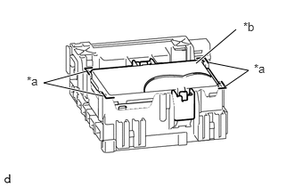
| *a | Driver Side junction block assembly enclosing wall |
| *b | Body Computer rear surface |
Check that the body computer rear surface and the driver side junction block assembly enclosing wall are at the same height.
- HINT:
-
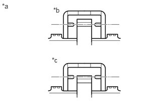 0.042,0.042 0.354,0.24 0.313,0.198 10 false *a 1.104,0.125 1.417,0.323 0.313,0.198 10 false *b 1.073,1.156 1.385,1.354 0.313,0.198 10 false *c
*a Upper view of Body Computer *b CORRECT *c INCORRECT
-
When the lock is engaged correctly, the tip of the body computer lock and the body computer lock engagement confirmation rib are in a straight line.
82673B
2.INSTALL JUNCTION BLOCK BRACKET (for Lower Side)
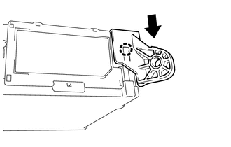
Engage the claw and install the junction block bracket (for lower side).
82673A
3.INSTALL JUNCTION BLOCK BRACKET (for Upper Side)
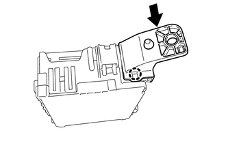
Engage the claw and install the junction block bracket (for upper side).
4.INSTALL WIRING HARNESS CLAMP BRACKET
Engage the pin and install the wiring harness bracket.
Install the bolt.
- Torque:
- 8.4 N*m (86 kgf*cm, 74 in.*lbf)
5.INSTALL DRIVER SIDE JUNCTION BLOCK ASSEMBLY WITH BODY COMPUTER (for RHD)
Connect the 8 connectors on the back side.
Install the driver side junction block assembly with body computer with the 2 nuts.
- Torque:
- 8.4 N*m (86 kgf*cm, 74 in.*lbf)
Engage the harness clamp.
Engage the harness clamp.
Connect the 9 connectors on the front side.
Engage the 3 harness clamps.
6.INSTALL DRIVER SIDE JUNCTION BLOCK ASSEMBLY WITH BODY COMPUTER (for LHD)
Connect the 8 connectors on the back side.
Install the driver side junction block assembly with body computer with the 2 nuts.
- Torque:
- 8.4 N*m (86 kgf*cm, 74 in.*lbf)
Engage the harness clamp.
Connect the 9 connectors on the front side.
Engage the 2 harness clamps.
7.INSTALL LOWER INSTRUMENT PANEL