Home › Audio / Visual / Telematics › PARK ASSIST / MONITORING › TOYOTA PARKING ASSIST-SENSOR SYSTEM › from 2017.10
RM30M0E _56 Audio / Visual / Telematics _068680 PARK ASSIST / MONITORING _0335855 TOYOTA PARKING ASSIST-SENSOR SYSTEM J

PARK ASSIST / MONITORING  TOYOTA PARKING ASSIST-SENSOR SYSTEM  Clearance Sonar Main Switch Circuit  


DESCRIPTION

When the back sonar or clearance sonar switch assembly is turned on, an on signal is sent to the clearance warning ECU assembly. The Toyota parking assist-sensor system operates according to this signal.

WIRING DIAGRAM
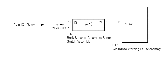
E318095E12
5.365,0.969 5.865,1.26 0.5,0.292 10 false CLSW 5.115,0.875 5.427,1.073 0.313,0.198 10 false 19 4.583,0.875 4.896,1.073 0.313,0.198 10 false 8 2.958,0.875 3.271,1.073 0.313,0.198 10 false 11 2.156,1.146 3.25,1.531 1.094,0.385 10 false ECU-IG NO. 1 0.594,0.99 1.719,1.198 1.125,0.208 10 false from IG1 Relay 2.927,1.396 4.25,1.604 1.323,0.208 10 false F175 2.906,1.563 4.854,2 1.948,0.438 10 false Back Sonar or Clearance Sonar Switch Assembly 4.885,1.885 6.208,2.094 1.323,0.208 10 false F176 4.896,2.052 7.094,2.323 2.198,0.271 10 false Clearance Warning ECU Assembly 4.198,0.885 4.615,1.198 0.417,0.313 10 false ECU 3.208,0.896 3.625,1.208 0.417,0.313 10 false IG

CAUTION / NOTICE / HINT

NOTICE:

Inspect the relay for circuits related to this system before performing the following procedure.


PROCEDURE
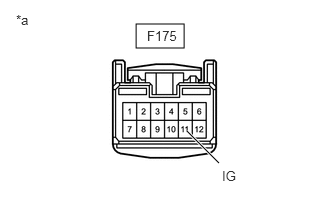
1.CHECK HARNESS AND CONNECTOR (BACK SONAR OR CLEARANCE SONAR SWITCH ASSEMBLY - BATTERY)
a.
E372616C03
1.417,0.25 1.917,0.5 0.5,0.25 1.948,1.365 2.281,1.698 true 1.531,0.292 2.042,0.563 0.51,0.271 10 false F175 0.167,0.125 0.479,0.323 0.313,0.198 10 false *a 2.313,1.75 2.823,2.021 0.51,0.271 10 false IG
*a Front view of wire harness connector
(to Back Sonar or Clearance Sonar Switch Assembly)


Disconnect the back sonar or clearance sonar switch assembly connector.


b.

Measure the voltage according to the value(s) in the table below.

Tester Connection Condition Specified Condition
F175-11 (IG) - Body ground Engine switch ON 11 to 14 V


Result:
Proceed to
OK
NG


OK

2.INSPECT BACK SONAR OR CLEARANCE SONAR SWITCH ASSEMBLY

NG

REPAIR OR REPLACE HARNESS OR CONNECTOR

2.INSPECT BACK SONAR OR CLEARANCE SONAR SWITCH ASSEMBLY
a.

Remove the back sonar or clearance sonar switch assembly.

Click hereAudio / Visual / Telematics>PARK ASSIST / MONITORING>CLEARANCE SONAR MAIN SWITCH>REMOVAL


b.

Inspect the back sonar or clearance sonar switch assembly.

Click hereAudio / Visual / Telematics>PARK ASSIST / MONITORING>CLEARANCE SONAR MAIN SWITCH>INSPECTION


Result:
Proceed to
OK
NG


OK

3.CHECK HARNESS AND CONNECTOR (BACK SONAR OR CLEARANCE SONAR SWITCH ASSEMBLY - CLEARANCE WARNING ECU ASSEMBLY)

NG

REPLACE BACK SONAR OR CLEARANCE SONAR SWITCH ASSEMBLY

3.CHECK HARNESS AND CONNECTOR (BACK SONAR OR CLEARANCE SONAR SWITCH ASSEMBLY - CLEARANCE WARNING ECU ASSEMBLY)
a.

Disconnect the F175 back sonar or clearance sonar switch assembly connector.


b.

Disconnect the F176 clearance warning ECU assembly connector.


c.

Measure the voltage according to the value(s) in the table below.

Standard Voltage:
Tester Connection Condition Specified Condition
F175-8 (ECU) - F176-19 (CLSW) Always Below 1 Ω
F175-8 (ECU) or F176-19 (CLSW) - Body ground Always 10 kΩ or higher


Result:
Proceed to
OK
NG


OK

PROCEED TO NEXT SUSPECTED AREA SHOWN IN PROBLEM SYMPTOMS TABLE

NG

REPAIR OR REPLACE HARNESS OR CONNECTOR