SUPPLEMENTAL RESTRAINT SYSTEMS SPIRAL CABLE INSTALLATION
CAUTION / NOTICE / HINT
- CAUTION:
-
Some of these service operations affect the SRS airbag system. Read the precautionary notices concerning the SRS airbag system before servicing.
-
Click hereVehicle Interior>SUPPLEMENTAL RESTRAINT SYSTEMS>AIRBAG SYSTEM>PRECAUTION
- HINT:
- ·
Use the same procedure for RHD and LHD vehicles.
·The following procedure is for LHD vehicles.
PROCEDURE

 84306
1.INSPECT SPIRAL CABLE SUB-ASSEMBLY
- NOTICE:
-
If the steering sensor is installed to a misaligned spiral cable, DTCs for an abnormal steering sensor value such as DTC C1290, C1439 are stored and it is impossible to repair them. If this happens, replace the spiral cable sub-assembly with a new one.
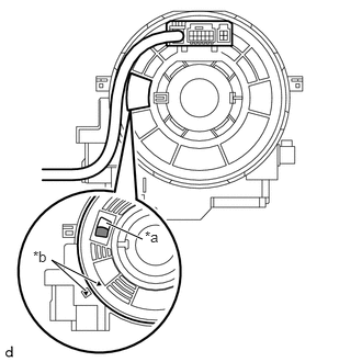
| *a | Check Window |
| *b | Matchmark |

|
U-Turn Point |
Check the check window shown in the illustration.
With the steering wheel straight ahead, align the matchmarks to check the U-turn point of the cable from the check window.
- NOTICE:
-
When the conditions above cannot be checked via the check window with the front wheels facing straight ahead, there may be a malfunction in the spiral cable. In this case, replace the spiral cable sensor sub-assembly with a new one.
If the spiral cable is not centered, center it.

|
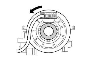
Interlock |
While pushing on the interlock indicated in the illustration, rotate the spiral cable counterclockwise slowly by hand until it stops.
- NOTICE:
- ·
When rotating the spiral cable, make sure to push on the interlock indicated in the illustration to release the interlock mechanism.
·Do not turn the spiral cable using the airbag wire harness.
|
|
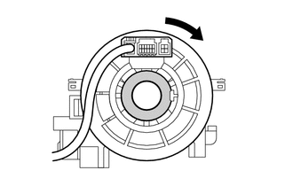
Interlock |
While pushing on the interlock indicated in the illustration, rotate the spiral cable 2.5 times clockwise from the lock position.
- HINT:
-
The spiral cable will rotate approximately 2.5 turns to both the left and right from the center.
| *a | Check Window |
| *b | Matchmark |
|
|
U-Turn Point |
Check the check window shown in the illustration.
With the steering wheel straight ahead, align the matchmarks to check the U-turn point of the cable from the check window.
- NOTICE:
-
When the conditions above cannot be checked via the check window with the front wheels facing straight ahead, there may be a malfunction in the spiral cable. In this case, replace the spiral cable sub-assembly with a new one.
84306
2.INSTALL SPIRAL CABLE SUB-ASSEMBLY (w/ VSC)
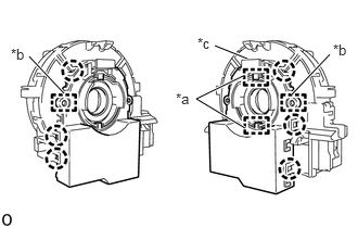
| *a | Guide |
| *b | Pin |
| *c | Lock Pin |
Align the 2 pins and 2 guides, and engage the 6 claws to install the steering sensor to the spiral cable sub-assembly.
- NOTICE:
- ·
Do not remove the lock pin before the steering sensor is installed to the spiral cable sub-assembly.
·Do not damage the pins of the spiral cable sub-assembly or guides of the steering sensor.
·The spiral cable sub-assembly can be rotated up to 30° even when the interlock is engaged. Therefore, make sure that both guides are aligned properly when installing the steering sensor to the spiral cable sub-assembly.
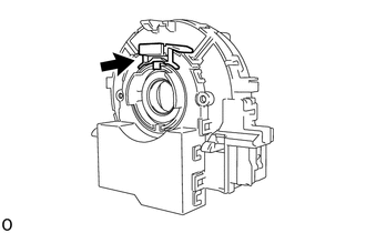
Remove the lock pin from the steering sensor.
84307
3.INSTALL SPIRAL CABLE WITH SENSOR SUB-ASSEMBLY (w/ VSC)
Check that the ignition switch is off.
Check that the cable is disconnected from the negative (-) battery terminal.
- CAUTION:
-
Wait at least 90 seconds after disconnecting the cable from the negative (-) battery terminal to disable the SRS system.
Check that the front wheels are facing straight ahead.
Set the turn signal switch to the neutral position.
- NOTICE:
-
If it is not in the neutral position, the turn signal switch pin may snap.
Engage the 3 claws to install the spiral cable with sensor sub-assembly.
- NOTICE:
-
Pull the lock pin out before installing the steering wheel assembly when replacing the spiral cable with sensor sub-assembly with a new one.
Connect the connectors to the spiral cable with sensor sub-assembly.
4.INSTALL SPIRAL CABLE SUB-ASSEMBLY (w/o VSC)
Check that the ignition switch is off.
Check that the cable is disconnected from the negative (-) battery terminal.
- CAUTION:
-
Wait at least 90 seconds after disconnecting the cable from the negative (-) battery terminal to disable the SRS system.
Check that the front wheels are facing straight ahead.
Set the turn signal switch to the neutral position.
- NOTICE:
-
If it is not in the neutral position, the turn signal switch pin may snap.
Engage the 3 claws to install the spiral cable sub-assembly.
- NOTICE:
-
Pull the lock pin out before installing the steering wheel assembly when replacing the spiral cable with sensor sub-assembly with a new one.
Connect the connectors to the spiral cable sub-assembly.
45286B
5.INSTALL UPPER STEERING COLUMN COVER
45287
6.INSTALL LOWER STEERING COLUMN COVER
45289A
7.INSTALL STEERING COLUMN COVER SUPPORT (w/ Smart Entry and Start System)
55411G
8.INSTALL NO. 1 INSTRUMENT CLUSTER FINISH PANEL
55661A
9.INSTALL INSTRUMENT PANEL REGISTER BEZEL
84306
10.ADJUST SPIRAL CABLE SUB-ASSEMBLY
- NOTICE:
-
Do not adjust the spiral cable sub-assembly with the battery connected and the ignition switch to ON.
Check that the ignition switch is off.
Check that the cable is disconnected from the negative (-) battery terminal.
- CAUTION:
-
Wait at least 90 seconds after disconnecting the cable from the negative (-) battery terminal to disable the SRS system.
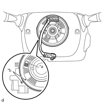
| *a | Check Window |
| *b | Matchmark |
|
|
U-Turn Point |
Check the check window shown in the illustration.
With the steering wheel straight ahead, align the matchmarks to check the U-turn point of the cable from the check window.
- NOTICE:
-
When the conditions above cannot be checked via the check window with the front wheels facing straight ahead, there may be a malfunction in the spiral cable sub-assembly. In this case, replace the spiral with cable sensor sub-assembly with a new one.
If the spiral cable sub-assembly is not centered, center it.
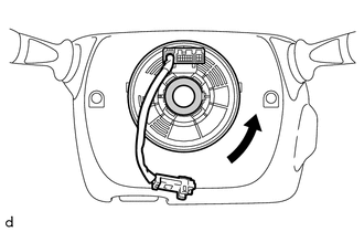
|
|
Interlock |
While pushing on the interlock indicated in the illustration, rotate the spiral cable sub-assembly counterclockwise slowly by hand until it stops.
- NOTICE:
- ·
When rotating the spiral cable sub-assembly, make sure to push on the interlock indicated in the illustration to release the interlock mechanism.
·Do not turn the spiral cable sub-assembly using the airbag wire harness.
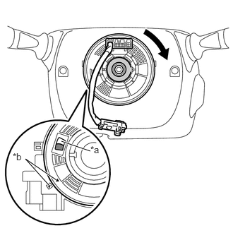
| *a | Check Window |
| *b | Matchmark |
|
|
U-Turn Point |
|
|
Interlock |
While pushing on the interlock indicated in the illustration, rotate the spiral cable sub-assembly 2.5 times clockwise from the lock position.
- HINT:
-
The spiral cable sub-assembly will rotate approximately 2.5 turns to both the left and right from the center.
Check the check window shown in the illustration.
With the steering wheel straight ahead, align the matchmarks to check the U-turn point of the cable from the check window.
If the cable cannot be centered, it is possible that the spiral cable sub-assembly is broken. Replace the spiral cable sub-assembly with a new one.
45100
11.INSTALL STEERING WHEEL ASSEMBLY
12.CONNECT CABLE TO NEGATIVE BATTERY TERMINAL
- Torque:
- 5.4 N*m (55 kgf*cm, 48 in.*lbf)
- NOTICE:
-
When disconnecting the cable, some systems need to be initialized after the cable is reconnected.
-
Click hereGeneral>INTRODUCTION>REPAIR INSTRUCTION>INITIALIZATION
13.INSPECT SRS WARNING LIGHT