INTERIOR PANELS / TRIM UPPER INSTRUMENT PANEL INSTALLATION
PROCEDURE

 55302A
1.INSTALL UPPER INSTRUMENT PANEL SUB-ASSEMBLY
Using a nipper, cut off both ends of the runner portion shown in the illustration (When installing a new one).
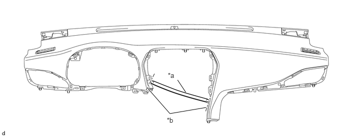
| *a | Runner Portion | *b | Cut Off |
Engage the 5 guides.
Engage the 10 clips and 2 dual lock fasteners to temporarily install the upper instrument panel sub-assembly.
- NOTICE:
- ·
Do not damage the upper instrument panel sub-assembly.
·Do not allow the wire harnesses to interfere with the surrounding parts.
Install the 2 clips.
Install the bolt <C> and screw <A>.
- Torque:
- Bolt <C> : 16 N*m (163 kgf*cm, 12 ft.*lbf)
w/ Wire Harness:
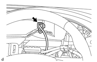
Connect the connector.
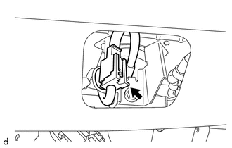
Connect the connector.
- NOTICE:
-
When connecting any airbag connector, take care not to damage the airbag wire harness.
55433B
2.INSTALL LOWER NO. 2 INSTRUMENT PANEL FINISH PANEL (for LHD)
w/ Smart Entry and Start System:
Connect the connector.
Engage the 5 clips to install the lower No. 2 instrument panel finish panel.
w/o Smart Entry and Start System:
Engage the 5 clips to install the lower No. 2 instrument panel finish panel.
58816D
3.INSTALL NO. 1 FRONT CONSOLE BOX INSERT (for LHD)
Engage the 2 claws and 4 guides to install the No. 1 front console box insert.
Install the 4 screws.
Install the clip.
58910C
4.INSTALL REAR CONSOLE BOX ASSEMBLY (for LHD)
55318C
5.INSTALL INSTRUMENT SIDE PANEL LH
Engage the 6 claws and 4 guides to install the instrument side panel LH.
55317A
6.INSTALL INSTRUMENT SIDE PANEL RH
- HINT:
-
Use the same procedure as for the LH side.
73900
7.INSTALL LOWER NO. 1 INSTRUMENT PANEL AIRBAG ASSEMBLY (for LHD with Driver Side Knee Airbag)
55432B
8.INSTALL LOWER INSTRUMENT PANEL FINISH PANEL (for LHD without Driver Side Knee Airbag)
Engage the 7 clips to install the lower instrument panel finish panel.
55480D
9.INSTALL LOWER INSTRUMENT PANEL FINISH PANEL ASSEMBLY
Connect the connectors.
Engage the 10 clips to install the lower instrument panel finish panel assembly.
Install the screw<B>.
55606
10.INSTALL NO. 1 INSTRUMENT PANEL UNDER COVER SUB-ASSEMBLY
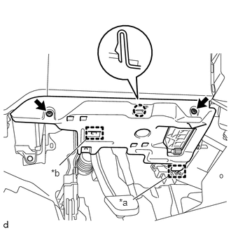
| *a | Guide |
| *b | Clamp |
Engage the claw, guide and clamp to install the No. 1 instrument panel under cover sub-assembly.
Install the 2 screws<B>.
55662A
11.INSTALL NO. 2 INSTRUMENT PANEL REGISTER BEZEL
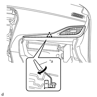
| *a | Clip |
for RHD:
Twist the clip in the direction indicated by the arrow to engage the clip.
Engage the 2 claws and 6 clips to install the No. 2 instrument panel register bezel.
for LHD:
Engage the 2 claws and 6 clips to install the No. 2 instrument panel register bezel.
55550
12.INSTALL GLOVE COMPARTMENT DOOR ASSEMBLY
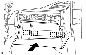
With the glove compartment door assembly opened approximately 60° from its closed position, engage the 4 hinges horizontally.
- NOTICE:
- ·
Engaging the hinges from the top will deform the hinges.
·Be sure to install the glove compartment door assembly horizontally.
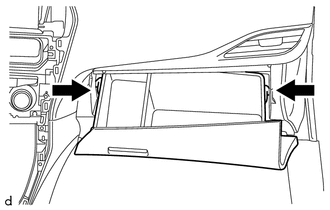
While pushing in the sides of the glove compartment door assembly as indicated by the arrows in the illustration, close the door to engage it to the 2 stoppers.
Engage the claw to connect the glove compartment door stopper sub-assembly.
83100
13.INSTALL COMBINATION METER ASSEMBLY
55411G
14.INSTALL NO. 1 INSTRUMENT CLUSTER FINISH PANEL (for LHD)
Engage the 6 clips to install the No. 1 instrument cluster finish panel.
55411G
15.INSTALL NO. 1 INSTRUMENT CLUSTER FINISH PANEL (for RHD)
Engage the 7 clips to install the No. 1 instrument cluster finish panel.
55661A
16.INSTALL INSTRUMENT PANEL REGISTER BEZEL
Engage the 5 clips and claw to install the instrument panel register bezel.
17.INSTALL RADIO RECEIVER ASSEMBLY WITH BRACKET (w/ Radio Receiver)
55412D
18.INSTALL CENTER INSTRUMENT CLUSTER FINISH PANEL (w/o Radio Receiver)
Engage the 7 clips to install the center instrument cluster finish panel.
Install the 4 screws.
55900
19.INSTALL AIR CONDITIONING CONTROL ASSEMBLY (w/o Radio Receiver)
55046A
20.INSTALL LOWER INSTRUMENT PANEL FINISH PANEL SUB-ASSEMBLY LH
Engage the 7 clips and claw to install the lower instrument panel finish panel sub-assembly LH.
Remove the protective tape.
55045A
21.INSTALL LOWER INSTRUMENT PANEL FINISH PANEL SUB-ASSEMBLY RH
- HINT:
-
Use the same procedure as for the LH side.
55409F
22.INSTALL NO. 2 INSTRUMENT PANEL SPEAKER PANEL SUB-ASSEMBLY
Engage the 2 clips and 2 guides to install the No. 2 instrument panel speaker panel sub-assembly.
55408F
23.INSTALL NO. 1 INSTRUMENT PANEL SPEAKER PANEL SUB-ASSEMBLY
- HINT:
-
Use the same procedure as for the No. 2 side.
62212
24.INSTALL FRONT PILLAR GARNISH LH (w/ Curtain Shield Airbag)
62211
25.INSTALL FRONT PILLAR GARNISH RH (w/ Curtain Shield Airbag)
- HINT:
-
Use the same procedure as for the LH side.
62212
26.INSTALL FRONT PILLAR GARNISH LH (w/o Curtain Shield Airbag)
62211
27.INSTALL FRONT PILLAR GARNISH RH (w/o Curtain Shield Airbag)
- HINT:
-
Use the same procedure as for the LH side.
62312B
28.INSTALL FRONT DOOR OPENING TRIM WEATHERSTRIP LH
Install the front door opening trim weatherstrip LH.
62311B
29.INSTALL FRONT DOOR OPENING TRIM WEATHERSTRIP RH
- HINT:
-
Use the same procedure as for the LH side.
30.CONNECT CABLE FROM NEGATIVE BATTERY TERMINAL
- Torque:
- 5.4 N*m (55 kgf*cm, 48 in.*lbf)
- NOTICE:
-
When disconnecting the cable, some systems need to be initialized after the cable is reconnected.
-
Click hereGeneral>INTRODUCTION>REPAIR INSTRUCTION>INITIALIZATION
31.INSPECT SRS WARNING LIGHT