HEATING / AIR CONDITIONING AIR CONDITIONING UNIT INSTALLATION
CAUTION / NOTICE / HINT
- HINT:
- ·
Use the same procedure for RHD and LHD vehicles.
·The procedure listed below is for LHD vehicles.
PROCEDURE

 87211G
1.INSTALL NO. 5 AIR DUCT
Engage the 3 claws and install a new No. 5 air duct.
87010
2.INSTALL AIR CONDITIONING UNIT ASSEMBLY
Connect the connector.
Temporarily install the air conditioning unit assembly to the vehicle body.
Install a new nut.
Install the bolt.
- Torque:
- for Bolt : 9.8 N*m (100 kgf*cm, 87 in.*lbf)
Install the 2 screws.
- Torque:
- 4.0 N*m (41 kgf*cm, 35 in.*lbf)
Connect the connector.
for LHD:
Engage the clamp.
for RHD:
Engage the 2 clamps.
87165C
3.INSTALL BLOWER MOTOR CONTROL (for Automatic Air Conditioning System)
87138C
4.INSTALL BLOWER RESISTOR (for Manual Air Conditioning System)
88650N
5.INSTALL AIR CONDITIONING AMPLIFIER ASSEMBLY (for Automatic Air Conditioning System)
88650N
6.INSTALL AIR CONDITIONING AMPLIFIER ASSEMBLY (for Manual Air Conditioning System)
88539C
7.INSTALL NO. 2 COOLER UNIT DRAIN HOSE
Install the No. 2 cooler unit drain hose with the clip.
88539
8.INSTALL NO. 1 COOLER UNIT DRAIN HOSE
Install the No. 1 cooler unit drain hose.
55306A
9.INSTALL NO. 1 INSTRUMENT PANEL BRACE SUB-ASSEMBLY
Install the No. 1 instrument panel brace sub-assembly with the bolt, nut and screw.
- Torque:
- Screw : 4.0 N*m (41 kgf*cm, 35 in.*lbf)
Engage the 2 clamps.
Return the front floor carpet assembly and install the clip.
Engage the front floor carpet assembly.
87211C
10.INSTALL NO. 4 AIR DUCT
Engage the 3 claws and install a new No. 4 air duct.
87245
11.CONNECT HEATER WATER INLET HOSE
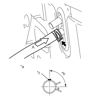
| *a | View A |
| *b | 90° |
| *c | Yellow Paint Mark |
Connect the heater water inlet hose to the heater radiator assembly with the hose clip.
- HINT:
-
Perform the installation with the hose clip and paint mark at the correct angle.
87246
12.CONNECT HEATER WATER OUTLET HOSE
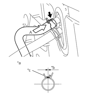
| *a | View A |
| *b | 0° |
| *c | White Paint Mark |
Connect the heater water outlet hose to the heater radiator assembly with the hose clip.
- HINT:
-
Perform the installation with the hose clip and paint mark at the correct angle.
88706A
13.CONNECT LIQUID TUBE SUB-ASSEMBLY A (w/ Cooler System)
Remove the vinyl tape from liquid tube sub-assembly A and connecting portion of the air conditioning unit assembly.
Apply sufficient compressor oil to a new O-ring and connecting part of the liquid tube sub-assembly A.
- Compressor oil:
ND-OIL 8 or equivalent
Install the O-ring onto the liquid tube sub-assembly A.
Connect the liquid tube sub-assembly A to the air conditioning unit assembly.
88712
14.CONNECT NO. 1 COOLER REFRIGERANT SUCTION HOSE (w/ Cooler System)
Remove the vinyl tape from No. 1 cooler refrigerant suction hose and connecting portion of the air conditioning unit assembly.
Apply sufficient compressor oil to a new O-ring and connecting part of the No. 1 cooler refrigerant suction hose.
- Compressor oil:
ND-OIL 8 or equivalent
Install the O-ring onto the No. 1 cooler refrigerant suction hose.
Connect the No. 1 cooler refrigerant suction hose.
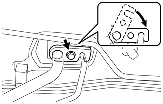
Turn the hook connector in the direction indicated by the arrow in the illustration.
Insert the pipe joints securely into the fitting holes and tighten the bolt.
- Torque:
- 9.8 N*m (100 kgf*cm, 87 in.*lbf)
88482
15.INSTALL COOLER CAP (w/o Cooler System)
Remove the vinyl tape from cooler cap and connecting portion of the air conditioning unit assembly.
Apply sufficient compressor oil to a new O-ring and connecting part of the cooler cap.
- Compressor oil:
ND-OIL 8 or equivalent
Install the O-ring onto the cooler cap.
Install the cooler cap with the bolt.
- Torque:
- 9.8 N*m (100 kgf*cm, 87 in.*lbf)
16.INSTALL STEERING COLUMN ASSEMBLY
89170A
17.INSTALL AIRBAG ECU ASSEMBLY
55303B
18.INSTALL LOWER INSTRUMENT PANEL SUB-ASSEMBLY
19.ADD ENGINE COOLANT
for 2NR-FE:
Click hereEngine / Hybrid System>2NR-FE COOLING>COOLANT>REPLACEMENT
for 1NR-FE:
Click hereEngine / Hybrid System>1NR-FE COOLING>COOLANT>REPLACEMENT
20.INSPECT COOLANT LEAK
for 2NR-FE:
Click hereEngine / Hybrid System>2NR-FE COOLING>COOLANT>REPLACEMENT
for 1NR-FE:
Click hereEngine / Hybrid System>1NR-FE COOLING>COOLANT>REPLACEMENT
21.CHARGE AIR CONDITIONING SYSTEM WITH REFRIGERANT
22.WARM UP ENGINE
23.INSPECT FOR REFRIGERANT LEAK