K320 MULTIDRIVE / CVT CONTINUOUSLY VARIABLE TRANSAXLE SYSTEM Shift Paddle Switch Circuit
DESCRIPTION
Moving the shift lever to M enables the shift range to be selected. The shift range can be selected by operating the "+" or "-" shift paddle switch.
WIRING DIAGRAM
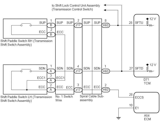
CAUTION / NOTICE / HINT
- NOTICE:
- ·
After the ignition switch is turned off, there may be a waiting time before disconnecting the negative (-) battery terminal.
Click hereGeneral>SETUP>WHEN DISCONNECTING OR RECONNECTING BATTERY TERMINAL>BEFORE DISCONNECTING BATTERY
·When disconnecting and reconnecting the battery.
Click hereGeneral>SETUP>WHEN DISCONNECTING OR RECONNECTING BATTERY TERMINAL>WORK PROCEDURE
- HINT:
-
When disconnecting and reconnecting the battery, there is an automatic learning function that completes learning when the respective system is used.
-
Click hereGeneral>SETUP>WHEN DISCONNECTING OR RECONNECTING BATTERY TERMINAL>AUTOMATIC LEARNING CHART
PROCEDURE
According to the display on the GTS, read the Data List.
- Powertrain > Transmission > Data List
-
Tester Display Measurement Item Range Normal Condition Diagnostic Note Sport Shift Up SW Sport shift up switch status ON or OFF ·ON: Shift lever held in "+" or "+" shift paddle switch operated
·OFF: Shift lever not held in "+" and "+" shift paddle switch released
- Sport Shift Down SW Sport shift down switch status ON or OFF ·ON: Shift lever held in "-" or "-" shift paddle switch operated
·OFF: Shift lever not held in "-" and "-" shift paddle switch released
-
- Powertrain > Transmission > Data List
-
Tester Display Sport Shift Up SW Sport Shift Down SW - 50003 373 26,25
- Result:
Result Proceed to Data List values are normal A Data List values are not normal B
A
B
Disconnect the TCM connector.
Disconnect the ECM connector.
Measure the resistance according to the value(s) in the table below.
- Standard Resistance:
Tester Connection Condition Specified Condition D71-28 (SFTU) - A54-28 (ECCS) "+" (Up shift) shift paddle switch operated and held Below 2.5 Ω "+" (Up shift) shift paddle switch not operated 1 MΩ or higher D71-27 (SFTD) - A54-28 (ECCS) "-" (Down shift) shift paddle switch operated and held Below 2.5 Ω "-" (Down shift) shift paddle switch not operated 1 MΩ or higher
Connect the ECM connector.
Connect the TCM connector.
- Result:
Proceed to OK NG
OK
NG
Disconnect the ECM connector.
Measure the resistance according to the value(s) in the table below.
- Standard Resistance:
Tester Connection Condition Specified Condition A54-10 (E1) - Body ground Always Below 1 Ω
Connect the ECM connector.
- Result:
Proceed to OK NG
OK
NG
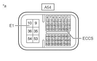
| *a | Component without harness connected
(ECM) |
Disconnect the ECM connector.
Measure the resistance according to the value(s) in the table below.
- Standard Resistance:
Tester Connection Condition Specified Condition A54-28 (ECCS) - A54-10 (E1) Always Below 1 Ω
Connect the ECM connector.
- Result:
Proceed to OK NG
OK
NG
NEXT
for Registration: Click hereDrivetrain>K320 (MULTIDRIVE / CVT)>CONTINUOUSLY VARIABLE TRANSAXLE SYSTEM>REGISTRATION
for Initialization: Click hereDrivetrain>K320 (MULTIDRIVE / CVT)>CONTINUOUSLY VARIABLE TRANSAXLE SYSTEM>INITIALIZATION
NEXT
Disconnect the spiral cable sub-assembly connector.
Disconnect the TCM connector.
Disconnect the ECM connector.
Measure the resistance according to the value(s) in the table below.
- Standard Resistance:
Tester Connection Condition Specified Condition D71-28 (SFTU) - H60-8 (SUP) Always Below 1 Ω D71-27 (SFTD) - H60-1 (SDN) Always Below 1 Ω A54-28 (ECCS) - H60-2 (ECC) Always Below 1 Ω D71-28 (SFTU) or H60-8 (SUP) - Body ground Always 10 kΩ or higher D71-27 (SFTD) or H60-1 (SDN) - Body ground Always 10 kΩ or higher A54-28 (ECCS) or H60-2 (ECC) - Body ground Always 10 kΩ or higher
Connect the ECM connector.
Connect the TCM connector.
Connect the spiral cable sub-assembly connector.
- Result:
Proceed to OK NG
OK
NG
Click hereVehicle Interior>SUPPLEMENTAL RESTRAINT SYSTEMS>SPIRAL CABLE>REMOVAL
- Result:
Proceed to OK NG
OK
NG
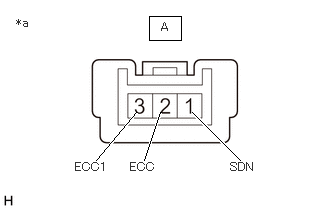
| *a | Component without harness connected
(Shift Paddle Switch LH (Transmission Shift Switch Assembly)) |
Remove the shift paddle switch LH (transmission shift switch assembly).
Click hereDrivetrain>K320 (MULTIDRIVE / CVT)>SHIFT PADDLE SWITCH>REMOVAL
Measure the resistance according to the value(s) in the table below.
- Standard Resistance:
Tester Connection Condition Specified Condition A-1 (SDN) - A-2 (ECC) "-" (Down shift) shift paddle switch operated and held Below 2.5 Ω "-" (Down shift) shift paddle switch not operated 1 MΩ or higher A-1 (SDN) - A-3 (ECC1) "-" (Down shift) shift paddle switch operated and held Below 2.5 Ω "-" (Down shift) shift paddle switch not operated 1 MΩ or higher
- Result:
Proceed to OK NG
OK
NG
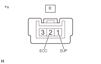
| *a | Component without harness connected
(Shift Paddle Switch RH (Transmission Shift Switch Assembly)) |
Remove the shift paddle switch RH (transmission shift switch assembly).
Click hereDrivetrain>K320 (MULTIDRIVE / CVT)>SHIFT PADDLE SWITCH>REMOVAL
Measure the resistance according to the value(s) in the table below.
- Standard Resistance:
Tester Connection Condition Specified Condition B-1 (SUP) - B-2 (ECC) "+" (Up shift) shift paddle switch operated and held Below 2.5 Ω "+" (Up shift) shift paddle switch not operated 1 MΩ or higher
- Result:
Proceed to OK NG
OK
NG
Install the shift paddle switch LH (transmission shift switch assembly) and shift paddle switch RH (transmission shift switch assembly).
Click hereDrivetrain>K320 (MULTIDRIVE / CVT)>SHIFT PADDLE SWITCH>INSTALLATION
Disconnect the No. 1 switch wire connector.
Measure the resistance according to the value(s) in the table below.
- Standard Resistance:
Tester Connection Condition Specified Condition z17-2 (SUP) - z17-3 (ECC) "+" (Up shift) shift paddle switch operated and held Below 2.5 Ω "+" (Up shift) shift paddle switch not operated 1 MΩ or higher z17-4 (SDN) - z17-3 (ECC) "-" (Down shift) shift paddle switch operated and held Below 2.5 Ω "-" (Down shift) shift paddle switch not operated 1 MΩ or higher
- Result:
Proceed to OK NG
OK
NG
NEXT
for Registration: Click hereDrivetrain>K320 (MULTIDRIVE / CVT)>CONTINUOUSLY VARIABLE TRANSAXLE SYSTEM>REGISTRATION
for Initialization: Click hereDrivetrain>K320 (MULTIDRIVE / CVT)>CONTINUOUSLY VARIABLE TRANSAXLE SYSTEM>INITIALIZATION