POWER DISTRIBUTION INTEGRATION RELAY INSTALLATION
PROCEDURE

 82644
1.INSTALL SEMICONDUCTOR POWER INTEGRATION ECU
- NOTICE:
- ·
Make sure the connector terminal is free from oil and grease.
·Do not subject the semiconductor power integration ECU to any impact.
·Do not use a semiconductor power integration ECU that has been dropped.
·Do not disassemble the semiconductor power integration ECU.
·Make sure the lever connector is securely connected.
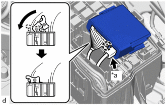
| *a | power source connector |
Connect the connector and pull down the lock lever to engage the claw and lock the connector as shown in the illustration.
Connect the power source connector.
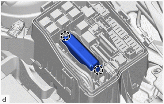
Engage the claws to install the semiconductor power integration ECU.
82662A
2.INSTALL NO. 1 RELAY BLOCK COVER
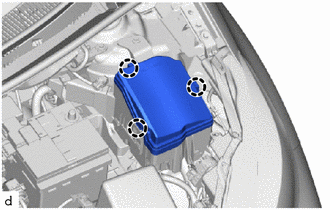
Engage the claws to install the No. 1 relay block cover.
3.CONNECT CABLE FROM NEGATIVE AUXILIARY BATTERY TERMINAL
for Gasoline Model:
Click hereGeneral>MAINTENANCE>M15A-FKS AUXILIARY BATTERY>INSTALLATION
for HV Model:
Click hereGeneral>MAINTENANCE>M15A-FXE AUXILIARY BATTERY>INSTALLATION
4. INITIALIZATION AFTER RECONNECTING AUXILIARY BATTERY TERMINAL
Click hereGeneral>SETUP>WHEN DISCONNECTING OR RECONNECTING BATTERY TERMINAL>WORK PROCEDURE
- HINT:
-
When disconnecting and reconnecting the auxiliary battery, there is an automatic learning function that completes learning when the respective system is used.
-
Click hereGeneral>SETUP>WHEN DISCONNECTING OR RECONNECTING BATTERY TERMINAL>AUTOMATIC LEARNING CHART