AUDIO / VIDEO RADIO ANTENNA CORD INSTALLATION
PROCEDURE

 86101Q
1.INSTALL NO. 4 ANTENNA CORD SUB-ASSEMBLY
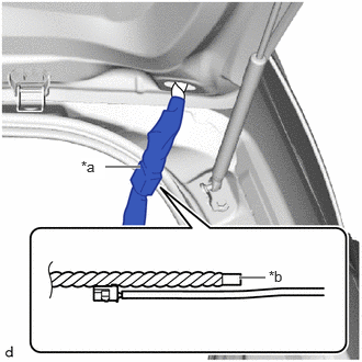
| *a | Nonwoven Tape |
| *b | Rope |
Secure a rope to the No. 4 antenna cord sub-assembly with nonwoven tape as shown in the illustration.
- NOTICE:
- ·
As conduction performance may degrade if adhesive from the nonwoven tape contacts the connecting parts of the connector, cover the connector with a plastic bag or similar before applying the nonwoven tape.
·Make sure that the rope is secured with nonwoven tape to prevent the rope from separating from the No. 4 antenna cord sub-assembly when removing it.

|
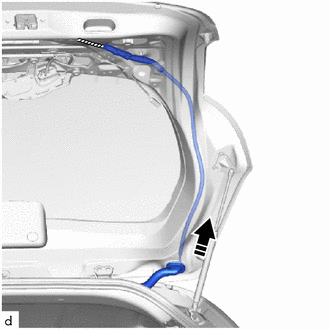
Install in this Direction |
Install the No. 4 antenna cord sub-assembly as shown in the illustration.
- NOTICE:
-
This step should not be performed with the back door panel sub-assembly removed from the vehicle.
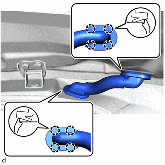
Engage the claws to install the 2 grommets.
Engage the clamp.
86101W
2.INSTALL NO. 7 ANTENNA CORD SUB-ASSEMBLY
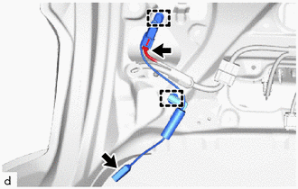
Engage the clamps to install the No. 7 antenna cord sub-assembly.
Connect the 2 connectors.
86101V
3.INSTALL NO. 6 ANTENNA CORD SUB-ASSEMBLY
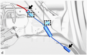
Engage the clamps to install the No. 6 antenna cord sub-assembly.
Connect the 2 connectors.
86101R
4.INSTALL NO. 5 ANTENNA CORD SUB-ASSEMBLY
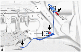
| *a | Clamp |
| *b | Guide |
Engage the guide.
Install the No. 5 antenna cord sub-assembly with the bolt.
- Torque:
- 10 N*m (102 kgf*cm, 7 ft.*lbf)
Engage the clamp.
Connect the 2 connectors.
67761A
5.INSTALL BACK DOOR TRIM COVER
67751
6.INSTALL BACK DOOR TRIM BOARD
86101J
7.INSTALL NO. 2 ANTENNA CORD SUB-ASSEMBLY
Align the marking tape (A) on the No. 2 antenna cord sub-assembly with the protrusion on the front of the roof headlining and wrap new adhesive tape around the No. 2 antenna cord sub-assembly and protrusion of the roof headlining.
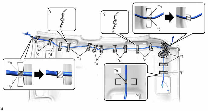
| *a | Marking Tape (A) | *b | Marking Tape (B) |
| *c | Marking Tape (C) | *d | Adhesive Tape (A) |
| *e | Adhesive Tape (B) | *f | Adhesive Tape (C) |
| *g | Adhesive Tape (D) | *h | Protrusion |
| *i | Dent in the Roof Headlining | - | - |

|
Adhesive Tape | 
|
Adjustment Area |
Apply the 3 new adhesive tapes (A) as shown in the illustration to secure the No. 2 antenna cord sub-assembly..
Align the No. 2 antenna cord sub-assembly with the dent in the roof headlining as shown in the illustration.
Apply the 8 new adhesive tapes (B) as shown in the illustration to secure the No. 2 antenna cord sub-assembly..
Align the marking tape (B) on the No. 2 antenna cord sub-assembly with the marking of the roof headlining.
Apply the 3 new adhesive tapes (C) as shown in the illustration to secure the No. 2 antenna cord sub-assembly..
- HINT:
- ·
Turn the connector contact surface upward and secure it with tape.
·Secure the extra length of the No. 2 antenna cord sub-assembly in the adjustment area as shown in the illustration.
Align the marking tape (C) on the No. 2 antenna cord sub-assembly with the protrusion on the front of the roof headlining and wrap new adhesive tape around the No. 2 antenna cord sub-assembly and protrusion of the roof headlining.
Apply the new adhesive tape (D) as shown in the illustration to secure the No. 2 antenna cord sub-assembly..
- HINT:
-
Secure the extra length of the No. 2 antenna cord sub-assembly in the adjustment area as shown in the illustration.
63311C
8.INSTALL ROOF HEADLINING
86101
9.INSTALL ANTENNA CORD SUB-ASSEMBLY
for Separate Type:
Engage the guides and clamps to install the antenna cord sub-assembly.
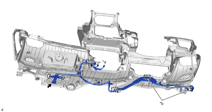
| *a | Clamp | *b | Guide |
Connect the connector.
Engage the claws.
for Integrated Type:
Engage the guide and clamps to install the antenna cord sub-assembly.
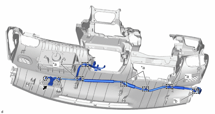
| *a | Clamp | *b | Guide |
Connect the connector.
Engage the claws.
55972C
10.INSTALL NO. 2 SIDE DEFROSTER NOZZLE DUCT
55971C
11.INSTALL NO. 1 SIDE DEFROSTER NOZZLE DUCT
55302C
12.INSTALL INSTRUMENT PANEL SUB-ASSEMBLY