INTERIOR PANELS / TRIM INSTRUMENT PANEL SAFETY PAD INSTALLATION
PROCEDURE

 55328
1.INSTALL NO. 1 INSTRUMENT PANEL PIN (for Separate Type)
- HINT:
-
Use the same procedure as for the opposite side.
Engage the guide.
Install the No. 1 instrument panel pin with the screw.
89120A
2.INSTALL AUTOMATIC LIGHT CONTROL SENSOR (for Separate Type)
55950G
3.INSTALL DEFROSTER NOZZLE ASSEMBLY (for Separate Type)
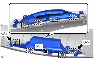
Engage the guides.
Install the defroster nozzle assembly with the 3 screws <A>.
55302C
4.INSTALL INSTRUMENT PANEL SUB-ASSEMBLY (for Integrated Type)
When installing a new instrument panel sub-assembly:
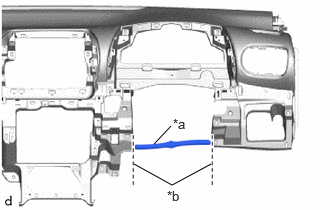
| *a | Runner Portion |
| *b | Cut Off |
Using a nipper, cut off both ends of the runner portion as shown in the illustration.
Engage the guides to install the instrument panel sub-assembly as shown in the illustration.
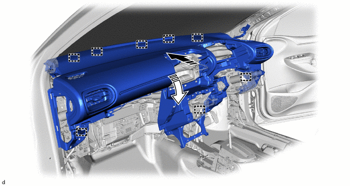

|
Install in this Direction (1) | 
|
Install in this Direction (2) |
Install the 3 bolts <F>, screw <E> and nut <I> as shown in the illustration.
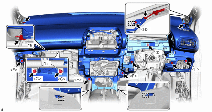
| *a | Airbag Connector | *b | Airbag Bolt |
Engage the hooks.
Install the 4 clips.
Connect the airbag connector.
- NOTICE:
-
When disconnecting any airbag connector, take care not to damage the airbag wire harness.
- HINT:
-
Refer to How to Connect or Disconnect Airbag Connector:
Install the 2 bolts <G>.
- Torque:
- 20 N*m (204 kgf*cm, 15 ft.*lbf)
Engage the guide and install the ground bracket with the bolt <H>.
- Torque:
- 10 N*m (102 kgf*cm, 7 ft.*lbf)
Connect the connector.
55302C
5.INSTALL INSTRUMENT PANEL SUB-ASSEMBLY (for Separate Type)
When installing a new instrument panel sub-assembly:
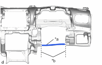
| *a | Runner Portion |
| *b | Cut Off |
Using a nipper, cut off both ends of the runner portion as shown in the illustration.
Engage the guides to install the instrument panel sub-assembly as shown in the illustration.
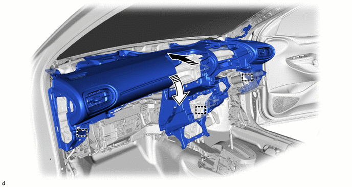
|
|
Install in this Direction (1) |
|
Install in this Direction (2) |
Install the 5 bolts <F>, screw <E> and nut <I> as shown in the illustration.
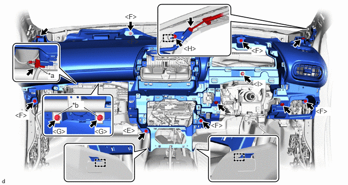
| *a | Airbag Connector | *b | Airbag Bolt |
Engage the hooks.
Install the 4 clips.
Connect the airbag connector.
- NOTICE:
-
When disconnecting any airbag connector, take care not to damage the airbag wire harness.
- HINT:
-
Refer to How to Connect or Disconnect Airbag Connector:
Install the 2 bolts <G>.
- Torque:
- 20 N*m (204 kgf*cm, 15 ft.*lbf)
Engage the guide and install the ground bracket with the bolt <H>.
- Torque:
- 10 N*m (102 kgf*cm, 7 ft.*lbf)
Connect the connector.
55313A
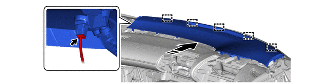
6.INSTALL INSTRUMENT MAIN PANEL (for Separate Type)
Engage the guides as shown in the illustration.
|
|
Install in this Direction | - | - |
Connect the connector.
Engage the clips and claws to install the instrument main panel as shown in the illustration.
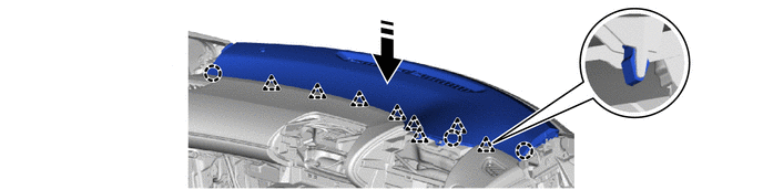
|
|
Install in this Direction | - | - |
55414A
7.INSTALL INSTRUMENT CLUSTER FINISH END PANEL (w/ Headup Display)
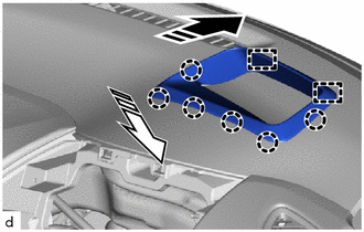
|
|
Install in this Direction (1) |
|
|
Install in this Direction (2) |
Engage the guides and claws to install the instrument cluster finish end panel as shown in the illustration.
55624A
8.INSTALL INSTRUMENT PANEL CENTER TRAY
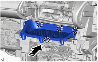
|
|
Install in this Direction |
Engage the claws to install the instrument panel center tray as shown in the illustration.
55420A
9.INSTALL INSTRUMENT CLUSTER FINISH CENTER PANEL ASSEMBLY
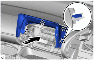
|
|
Install in this Direction |
Engage the clips to install the instrument cluster finish center panel assembly as shown in the illustration.
86140A
10.INSTALL RADIO AND DISPLAY RECEIVER ASSEMBLY WITH BRACKET
55670A
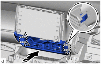
11.INSTALL INSTRUMENT PANEL CENTER REGISTER ASSEMBLY
Engage the clamp.
|
|
Install in this Direction |
Engage the guides and clips to install the instrument panel center register assembly as shown in the illustration.
55405B
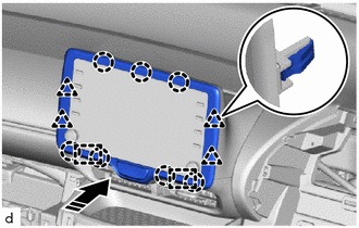
12.INSTALL INSTRUMENT CLUSTER FINISH CENTER PANEL SUB-ASSEMBLY
Connect the connector.
|
|
Install in this Direction |
Engage the guides, clips and claws to install the instrument cluster finish center panel sub-assembly as shown in the illustration.
55406B
13.INSTALL INSTRUMENT CLUSTER FINISH LOWER CENTER PANEL SUB-ASSEMBLY (for Manual Air Conditioning System)
55900
14.INSTALL AIR CONDITIONING CONTROL ASSEMBLY (for Automatic Air Conditioning System)
83100
15.INSTALL COMBINATION METER ASSEMBLY (for Analog Meter)
83100
16.INSTALL COMBINATION METER ASSEMBLY (for Digital Meter)
55410C
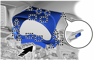
17.INSTALL INSTRUMENT CLUSTER FINISH PANEL ASSEMBLY (for Analog Meter)
|
|
Install in this Direction |
Engage the guides, clips and claws to install the instrument cluster finish panel assembly as shown in the illustration.
Install the 2 screws <A> or 2 screws <B>.
55410C
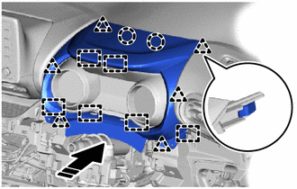
18.INSTALL INSTRUMENT CLUSTER FINISH PANEL ASSEMBLY (for Digital Meter)
|
|
Install in this Direction |
Engage the guides, clips and claws to install the instrument cluster finish panel assembly as shown in the illustration.
Install the 2 screws <A> or 2 screws <B>.
55548A
19.INSTALL INSTRUMENT PANEL HOLE COVER
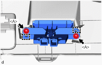
Engage the guides.
Install the instrument panel hole cover with the 2 screws <A>.
55480D
20.INSTALL LOWER INSTRUMENT PANEL FINISH PANEL ASSEMBLY
Connect each connector.
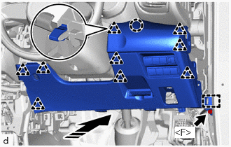
|
|
Install in this Direction |
Engage the guide, clips and claw to install the lower instrument panel finish panel assembly as shown in the illustration.
Install the bolt <F>.
53601
21.CONNECT HOOD LOCK CONTROL LEVER SUB-ASSEMBLY
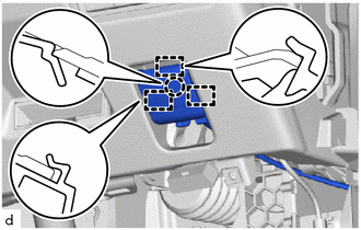
Engage the guides and claw to connect the hood lock control lever sub-assembly.
86160P
22.INSTALL FRONT NO. 2 SPEAKER ASSEMBLY (for 6 Speakers)
62211
23.INSTALL FRONT PILLAR GARNISH RH
Remove the adhesive tape and protective cover.
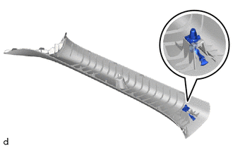
Install a new front pillar garnish clips to the front pillar garnish RH.
- NOTICE:
-
When installing the front pillar garnish clip, make sure to install it in the correct position and facing in the correct direction.
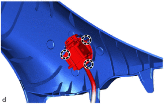
w/ Speaker:
Engage the claws to connect the front No.2 speaker assembly.
w/o Speaker:
Engage the clamp.
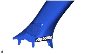

|
Protective Tape |
Apply protective tape to the locations shown in the illustration.
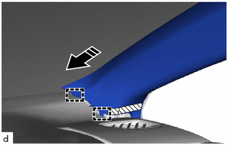
|
|
Install in this Direction |
Align the guides and partially engage the front pillar garnish RH.
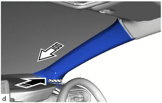
|
|
Install in this Direction (1) |
|
|
Install in this Direction (2) |
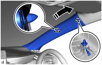
While holding down the tip of the front pillar garnish RH, push it in as shown in the illustration.
|
|
Install in this Direction |
Engage the front pillar garnish clip and clip to install the front pillar garnish RH as shown in the illustration.
62212
24.INSTALL FRONT PILLAR GARNISH LH
- HINT:
-
Use the same procedure as for the RH side.
55557A
25.INSTALL GLOVE COMPARTMENT DOOR CHECK CUSHION
- HINT:
-
Use the same procedure as for the opposite side.
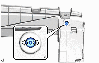
Engage the claws to install the glove compartment door check cushion.
55433B
26.INSTALL LOWER NO. 2 INSTRUMENT PANEL FINISH PANEL
|
|
Install in this Direction |
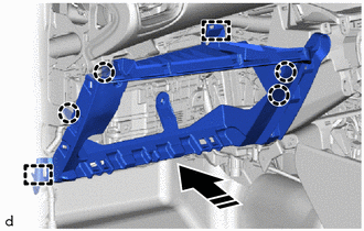
Engage the guides and claws to install the lower No. 2 instrument panel finish panel as shown in the illustration.
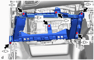
Install the 2 screws <C>, 3 screws <D> and screw <E>.
55550
27.INSTALL GLOVE COMPARTMENT DOOR ASSEMBLY
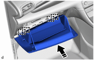
|
|
Install in this Direction |
Engage the hinges in the horizontal direction to install the glove compartment door assembly as shown in the illustration.
- NOTICE:
- ·
Engaging the hinges from the top will deform the hinges.
·Be sure to install the glove compartment door assembly horizontally.
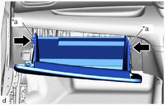
| *a | Stopper |

|
Push |
While pushing in the sides of the glove compartment door assembly as indicated by the arrows in the illustration, close the door to engage it to the 2 stoppers.
55317E
28.INSTALL NO. 1 INSTRUMENT SIDE PANEL
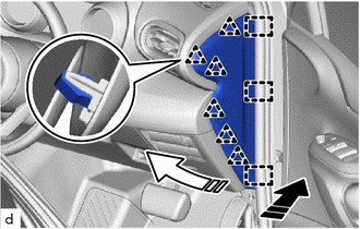
|
|
Install in this Direction (1) |
|
|
Install in this Direction (2) |
Engage the guides and clips to install the No. 1 instrument side panel as shown in the illustration.
55318F
29.INSTALL NO. 2 INSTRUMENT SIDE PANEL
- HINT:
-
Use the same procedure as for the RH side.
62311B
30.CONNECT FRONT DOOR OPENING TRIM WEATHERSTRIP RH
Connect the front door opening trim weatherstrip RH.
62312B
31.CONNECT FRONT DOOR OPENING TRIM WEATHERSTRIP LH
- HINT:
-
Use the same procedure as for the RH side.
55607
32.INSTALL NO. 2 INSTRUMENT PANEL UNDER COVER SUB-ASSEMBLY
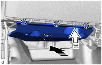
|
|
Install in this Direction (1) |
|
|
Install in this Direction (2) |
Engage the guide and claws to install the No. 2 instrument panel under cover sub-assembly as shown in the illustration.
55606
33.INSTALL NO. 1 INSTRUMENT PANEL UNDER COVER SUB-ASSEMBLY
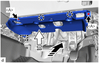
|
|
Install in this Direction (1) |
|
|
Install in this Direction (2) |
Engage the guide and claws as shown in the illustration.
Install the No. 1 instrument panel under cover sub-assembly with the 2 screws <A>.
62111C
34.INSTALL COWL SIDE TRIM BOARD RH
62112
35.INSTALL COWL SIDE TRIM BOARD LH
- HINT:
-
Use the same procedure as for the RH side.
67913B
36.INSTALL FRONT DOOR SCUFF PLATE RH
67914B
37.INSTALL FRONT DOOR SCUFF PLATE LH
- HINT:
-
Use the same procedure as for the RH side.
38.INSTALL HEADLIGHT DIMMER SWITCH ASSEMBLY
39.INSTALL REAR CONSOLE BOX ASSEMBLY
40.CONNECT CABLE TO NEGATIVE AUXILIARY BATTERY TERMINAL
for Gasoline Model:
Click hereGeneral>MAINTENANCE>M15A-FKS AUXILIARY BATTERY>INSTALLATION
for HV Model:
Click hereGeneral>MAINTENANCE>M15A-FXE AUXILIARY BATTERY>INSTALLATION
41. INITIALIZATION AFTER RECONNECTING AUXILIARY BATTERY TERMINAL
Click hereGeneral>SETUP>WHEN DISCONNECTING OR RECONNECTING BATTERY TERMINAL>WORK PROCEDURE
- HINT:
-
When disconnecting and reconnecting the auxiliary battery, there is an automatic learning function that completes learning when the respective system is used.
-
Click hereGeneral>SETUP>WHEN DISCONNECTING OR RECONNECTING BATTERY TERMINAL>AUTOMATIC LEARNING CHART