BRAKE CONTROL / DYNAMIC CONTROL SYSTEMS ELECTRONICALLY CONTROLLED BRAKE SYSTEM(for HV Model) C051223 Right Rear Wheel Speed Sensor Signal Stuck Low
DESCRIPTION
Refer to DTC C05121F.
| DTC No. | Detection Item | DTC Detection Condition | Trouble Area | DTC Output from |
|---|---|---|---|---|
| C051223 | Right Rear Wheel Speed Sensor Signal Stuck Low | Any of the following is detected:
·
At a vehicle speed of 10 km/h (6 mph) or more, output voltage from one of the speed sensors is less than that from the other sensors for 15 seconds or more. ·
At a vehicle speed of 10 km/h (6 mph) or more, outputs from both speed sensors are 0 km/h (0 mph) for 15 seconds or more. (except when both rear speed sensors are 0 km/h (0 mph)). ·
At a vehicle speed of 10 km/h (6 mph) or more, output from one of the speed sensors is 0 km/h (0 mph) for 1 second or more. |
·
Skid control sensor wire RH ·
Rear speed sensor RH (rear axle hub and bearing assembly RH) ·
Speed sensor installed improperly ·
Rear speed sensor rotor RH (rear axle hub and bearing assembly RH) ·
Wire harness or connector |
Brake |
WIRING DIAGRAM
Refer to DTC C05121F.
CAUTION / NOTICE / HINT
- NOTICE:
- ·
After replacing or removing and installing a speed sensor, perform Dealer Mode (Signal Check) inspection to confirm that the speed sensors are operating correctly.
·After replacing or removing and installing a speed sensor rotor, perform Dealer Mode (Signal Check) inspection to confirm that the speed sensors are operating correctly.
PROCEDURE
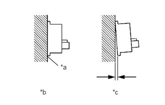
| *a | No clearance |
| *b | Correct |
| *c | Incorrect |
Turn the ignition switch off.
Check the rear speed sensor RH installation.
- OK:
There is no clearance between the rear speed sensor RH and the rear axle hub and bearing assembly RH.
- HINT:
-
The rear speed sensor rotor RH and rear speed sensor RH are incorporated into the rear axle hub and bearing assembly RH.
-
If the rear speed sensor rotor RH needs to be replaced, replace the rear axle hub and bearing assembly RH with rear speed sensor RH.
- Result:
Proceed to OK NG
OK
NG
Select the Data List on the GTS.
- Chassis > Brake > Data List
-
Tester Display Measurement Item Range Normal Condition Diagnostic Note RR Wheel Speed Rear wheel speed sensor RH reading Min.: 0.0 km/h (0.0 mph)
Max.: 6553.5 km/h (4072 mph)Vehicle stopped: 0.0 km/h (0.0 mph) When driving at constant speed: No large fluctuations
- Chassis > Brake > Data List
-
Tester Display RR Wheel Speed - 50003 435 15
Check the rear speed sensor RH output value.
- OK:
The output value changes in accordance with the vehicle speed.
- Result:
Proceed to OK NG
OK
Click hereGeneral>INTRODUCTION>HOW TO TROUBLESHOOT ECU CONTROLLED SYSTEMS>HOW TO PROCEED WITH TROUBLESHOOTING
NG
Turn the ignition switch off.
Make sure that there is no looseness at the locking part and the connecting part of the connectors.
- OK:
The connector is securely connected.
Disconnect the i1 and iO1 rear skid control sensor wire RH connector.
Check both the connector case and the terminals for deformation and corrosion.
- OK:
No deformation or corrosion.
Measure the resistance according to the value(s) in the table below.
- Standard Resistance:
Tester Connection Condition Specified Condition i1-2 (RR+) - iO1-2 (RR+) Always Below 1 Ω i1-2 (RR+) or iO1-2 (RR+) - Body ground and other terminals Always 10 kΩ or higher i1-1 (RR-) - iO1-1 (RR-) Always Below 1 Ω i1-1 (RR-) or iO1-1 (RR-) - Body ground and other terminals Always 10 kΩ or higher
- Result:
Proceed to OK NG
OK
NG
Make sure that there is no looseness at the locking part and the connecting part of the connectors.
- OK:
The connector is securely connected.
Disconnect the A38 skid control ECU (brake booster with master cylinder assembly) connector.
Check both the connector case and the terminals for deformation and corrosion.
- OK:
No deformation or corrosion.
Measure the resistance according to the value(s) in the table below.
- Standard Resistance:
Tester Connection Condition Specified Condition iO1-2 (RR+) - A38-7 (RR+) Always Below 1 Ω iO1-2 (RR+) or A38-7 (RR+) - Body ground and other terminals Always 10 kΩ or higher iO1-1 (RR-) - A38-8 (RR-) Always Below 1 Ω iO1-1 (RR-) or A38-8 (RR-) - Body ground and other terminals Always 10 kΩ or higher
- HINT:
-
The rear speed sensor RH is incorporated into the rear axle hub and bearing assembly RH.
-
If the rear speed sensor RH needs to be replaced, replace the rear axle hub and bearing assembly RH.
- Result:
Proceed to OK NG
OK
NG