CRUISE CONTROL LANE TRACING ASSIST SYSTEM Steering Vibration does not Operate
DESCRIPTION
The forward recognition camera communicates with the combination meter via CAN communication.
When steering assistance is activated due to operation of the lane departure restraint function or lane centering function, the combination meter activates the steering vibration.
WIRING DIAGRAM
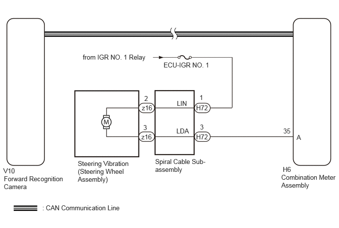
CAUTION / NOTICE / HINT
- NOTICE:
- ·
Inspect the fuses for circuits related to this system before performing the following
·The vehicle is equipped with a Supplemental Restraint System (SRS) which includes components such as airbags. Before servicing (including removal or installation of parts), be sure to read the precaution for Supplemental Restraint System.
Click hereVehicle Interior>SUPPLEMENTAL RESTRAINT SYSTEMS>AIRBAG SYSTEM>PRECAUTION
PROCEDURE
Check for DTCs.
- Chassis > Lane Control > Trouble Codes
- 50001 418
- Result:
Result Proceed to DTC U015587 is not output A DTC U015587 is output B
A
B
for HV Model: Click herePower Source / Network>NETWORKING>CAN COMMUNICATION SYSTEM (for HV Model)>HOW TO PROCEED WITH TROUBLESHOOTING
for Gasoline Model: Click herePower Source / Network>NETWORKING>CAN COMMUNICATION SYSTEM (for Gasoline Model)>HOW TO PROCEED WITH TROUBLESHOOTING
Click hereVehicle Interior>SUPPLEMENTAL RESTRAINT SYSTEMS>SPIRAL CABLE>INSPECTION
- Result:
Proceed to OK NG
OK
NG
Disconnect the H72 spiral cable sub-assembly connector.
Disconnect the H6 combination meter assembly connector.
Measure the resistance according to the value(s) in the table below.
- Standard Resistance:
Tester Connection Condition Specified Condition H72-3 (LDA) - H6-35 (A) Always Below 1 Ω H72-3 (LDA) or H6-35 (A) - Body ground Always 10 kΩ or higher
- Result:
Proceed to OK NG
OK
NG
Disconnect the H72 spiral cable sub-assembly connector.
Measure the voltage according to the value(s) in the table below.
- Standard Voltage:
Tester Connection Condition Specified Condition H72-1 (LIN) - Body ground Ignition switch off Below 1 V H72-1 (LIN) - Body ground Ignition switch ON 11 to 14 V
- Result:
Proceed to OK NG
OK
NG