REAR SUSPENSION REAR COIL SPRING(for TMC Made) REMOVAL
CAUTION / NOTICE / HINT
The necessary procedures (adjustment, calibration, initialization, or registration) that must be performed after parts are removed and installed, or replaced during the rear coil spring removal/installation are shown below.
| Replacement Part or Procedure | Necessary Procedures | Effect/Inoperative Function When Necessary Procedures are not Performed | Link |
|---|---|---|---|
| for HV Model:
Auxiliary battery terminal is disconnected/reconnected |
Memorize steering angle neutral point | Parking assist monitor system | ( ) |
| Rear wheel alignment adjustment | for HV Model:
1.
Perform "Reset Memory" 2.
Perform calibration (linear solenoid valve offset learning, SM solenoid valve offset learning, brake pedal stroke sensor assembly zero point calibration, system information memorization, and yaw rate and acceleration sensor zero point calibration) |
·
DTCs are stored ·
ABS warning light illuminates ·
Brake system warning light (yellow indicator) ·
Slip indicator light illuminates ·
VSC disabled or malfunctions |
()
|
| for Gasoline Model:
Calibration |
·
DTCs are stored ·
ABS warning light illuminates ·
Slip indicator light illuminates ·
VSC disabled or malfunctions |
()
|
|
| Suspension, tires, etc.
(The vehicle height changes because of suspension or tire replacement.) |
·
Ultrasonic sensor detection angle ·
Ultrasonic sensor detection angle registration |
Parking support brake system | ()
|
| Rear television camera assembly optical axis (Back camera position setting) | Parking assist monitor system | ()
|
- HINT:
- for HV Model
- ·
When the cable is disconnected/reconnected to the auxiliary battery terminal, systems temporarily stop operating. However, each system has a function that completes learning the first time the system is used.
-Learning completes when vehicle is driven
Effect/Inoperative Function When Necessary Procedures are not Performed Necessary Procedures Link Lane tracing assist system Drive the vehicle straight ahead at 35 km/h (22 mph) or more for 5 seconds or more. ( )
Pre-collision system
-Learning completes when vehicle is operated normally
Effect/Inoperative Function When Necessary Procedures are not Performed Necessary Procedures Link Power door lock control system
·Back door opener
Perform door unlock operation with door control switch or electrical key transmitter sub-assembly switch. ( )
Air conditioning system After the ignition switch is turned to ON, the servo motor standard position is recognized. -
- HINT:
- ·
Use the same procedure for the RH and LH sides.
·The following procedure is for the LH side.
PROCEDURE

 1. PRECAUTION (for HV Model)
- NOTICE:
-
After turning the ignition switch off, waiting time may be required before disconnecting the cable from the negative (-) auxiliary battery terminal.
-
Click hereGeneral>SETUP>WHEN DISCONNECTING OR RECONNECTING BATTERY TERMINAL>BEFORE DISCONNECTING BATTERY
2.DISABLE BRAKE CONTROL (for HV Model)
3.REMOVE REAR WHEEL
4.DRAIN BRAKE FLUID
- NOTICE:
-
Immediately wash off any brake fluid that comes into contact with any painted surfaces.
89516D
5.SEPARATE SKID CONTROL SENSOR WIRE LH
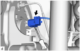
| *a | Protective Tape |
Using a screwdriver with its tip wrapped with protective tape, disengage the claw of the connector lock portion and disconnect the skid control sensor wire LH connector.
- NOTICE:
-
Do not remove the connector cover from the connector because the skid control sensor wire may be damaged.
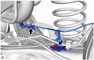
Remove the 2 nuts and separate the skid control sensor wire LH.
89516C
6.SEPARATE SKID CONTROL SENSOR WIRE RH
- HINT:
-
Perform the same procedure as for the LH side.
47319F
7.SEPARATE REAR FLEXIBLE HOSE LH
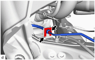
Using a union nut wrench 10 mm, disconnect the brake tube while holding the rear flexible hose with a wrench.
- NOTICE:
- ·
Do not kink or damage the brake line.
·Do not allow any foreign matter such as dirt and dust to enter the brake line.
Remove the clip and disconnect the rear flexible hose LH from the rear axle beam assembly.
47318F
8.SEPARATE REAR FLEXIBLE HOSE RH
- HINT:
-
Perform the same procedure as for the LH side.
46430
9.SEPARATE NO. 3 PARKING BRAKE CABLE ASSEMBLY
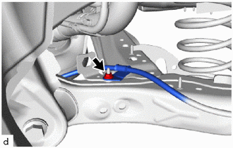
Remove the nut and separate the No. 3 parking brake cable assembly.
46420
10.SEPARATE NO. 2 PARKING BRAKE CABLE ASSEMBLY
- HINT:
-
Perform the same procedure as for the No. 3 side.
48231B
11.REMOVE REAR COIL SPRING LH
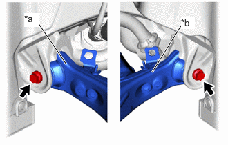
| *a | LH Side |
| *b | RH Side |
Loosen the 2 bolts.
- NOTICE:
-
Do not remove the bolts.
Support the spring seat of the rear axle beam assembly using 2 jacks and 2 wooden blocks.
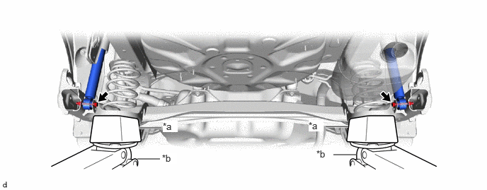
| *a | Wooden Block | *b | Jack |
- CAUTION:
-
Do not jack up the rear axle beam assembly too high as the vehicle may fall.
Remove the 2 bolts and 2 nuts, and separate the rear axle beam assembly from the rear shock absorber assemblies LH and RH.
- NOTICE:
-
Because the nut has its own stopper, do not turn the nut. Loosen the bolt with the nut fixed in place.
Slowly lower the rear axle beam assembly using 2 jacks and 2 wooden blocks, and remove the rear coil spring.
Slowly jack up the rear axle beam assembly using 2 jacks and 2 wooden blocks, and temporarily install the rear axle beam assembly to the rear shock absorber assemblies LH and RH with the 2 bolts and 2 nuts.
- NOTICE:
-
Because the nut has its own stopper, do not turn the nut. Tighten the bolt with the nut secured.
48259A
12.REMOVE REAR UPPER COIL SPRING INSULATOR
Remove the rear upper coil spring insulator.
48258C
13.REMOVE REAR LOWER COIL SPRING INSULATOR
Remove the rear lower coil spring insulator.