1KR-FE FUEL FUEL INJECTOR INSTALLATION
PROCEDURE

 23291
1.INSTALL INJECTOR VIBRATION INSULATOR
Install 6 new injector vibration insulators to the cylinder head sub-assembly.
23250
2.INSTALL FUEL INJECTOR ASSEMBLY
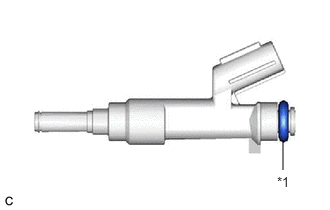
| *1 | O-ring |
Apply a light coat of gasoline or spindle oil to new O-rings, and then install one onto each fuel injector assembly.
Apply a light coat of gasoline or spindle oil where the fuel delivery pipe contacts each O-ring.
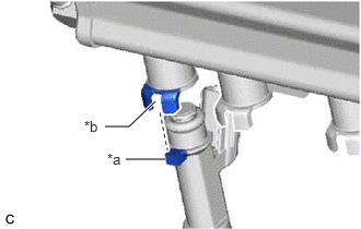
| *a | Protrusion |
| *b | Groove |
Align the protrusion of the fuel injector assembly with the groove of the fuel delivery pipe.
- NOTICE:
- ·
Do not damage the fuel injector assembly or O-ring.
·Do not twist the O-ring.
- HINT:
-
Use the same procedure to install the other fuel injector assemblies.
23845C
3.INSTALL FUEL PIPE INSULATOR
Install the 2 fuel pipe insulators to the fuel delivery pipe.
23814B
4.INSTALL FUEL DELIVERY PIPE
Place the fuel delivery pipe with the 6 fuel injector assemblies onto the cylinder head sub-assembly.
- NOTICE:
-
Do not drop the fuel injector assemblies when installing the fuel delivery pipe.
Install the fuel delivery pipe with the fuel injector assemblies with the 2 bolts.
- Torque:
- 27 N*m (275 kgf*cm, 20 ft.*lbf)
23901
5.CONNECT FUEL TUBE SUB-ASSEMBLY
Connect the fuel tube sub-assembly from the fuel delivery pipe.
Click hereEngine / Hybrid System>1KR-FE (FUEL)>FUEL SYSTEM>PRECAUTION
82121
6.CONNECT ENGINE WIRE
Engage the clamp.
Connect the 6 fuel injector assembly connectors.
17111
7.INSTALL INTAKE MANIFOLD
8.CONNECT CABLE TO NEGATIVE AUXILIARY BATTERY TERMINAL
9. INITIALIZATION AFTER RECONNECTING NEGATIVE AUXILIARY BATTERY TERMINAL
Click hereGeneral>SETUP>WHEN DISCONNECTING OR RECONNECTING BATTERY TERMINAL>WORK PROCEDURE
- HINT:
-
When disconnecting and reconnecting the battery, there is an automatic learning function that completes learning when the respective system is used.
-
Click hereGeneral>SETUP>WHEN DISCONNECTING OR RECONNECTING BATTERY TERMINAL>AUTOMATIC LEARNING CHART
10.INSPECT FOR FUEL LEAK