Home › Vehicle Interior › LIGHTING (INT) › LIGHTING SYSTEM › from 2020.07
RM36W0E _58 Vehicle Interior _087823 LIGHTING (INT) _0419674 LIGHTING SYSTEM J

LIGHTING (INT)  LIGHTING SYSTEM  Interior Light Circuit  


DESCRIPTION

The main body ECU (multiplex network body ECU) controls the operation of the following lights:

·

Map Light Assembly

·

Room Light Assembly*1


*1: w/ Room Light


WIRING DIAGRAM

w/ Room Light
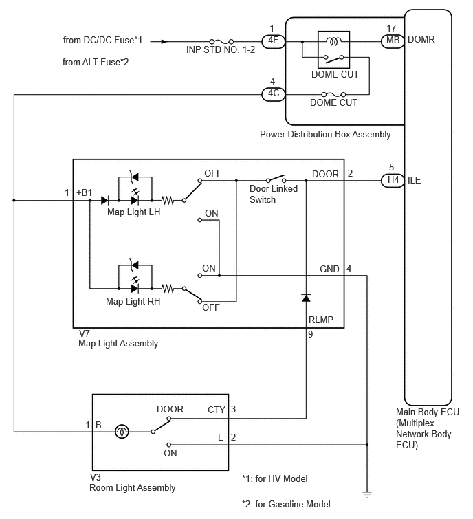

E438206E07
0.958,0.521 2.219,0.833 1.26,0.313 10 false from DC/DC Fuse*1 4.063,0.521 4.375,0.719 0.313,0.198 10 false 4F 4.083,0.344 4.396,0.542 0.313,0.198 10 false 1 4.063,1.323 4.375,1.521 0.313,0.198 10 false 4C 4.094,1.146 4.406,1.344 0.313,0.198 10 false 4 2.823,0.667 3.99,0.927 1.167,0.26 10 false INP STD NO. 1-2 4.719,1.042 5.948,1.24 1.229,0.198 10 false DOME CUT 5.854,0.344 6.167,0.542 0.313,0.198 10 false 17 5.896,2.448 6.052,2.646 0.156,0.198 10 false 5 6.177,2.646 6.635,2.844 0.458,0.198 10 false ILE 6.177,0.51 6.792,0.708 0.615,0.198 10 false DOMR 3.938,1.948 6.958,2.208 3.021,0.26 10 false Power Distribution Box Assembly 4.729,2.552 5.344,2.75 0.615,0.198 10 false DOOR 4.844,3.99 5.302,4.188 0.458,0.198 10 false GND 5.25,3.979 5.563,4.177 0.313,0.198 10 false 4 5.271,2.542 5.427,2.74 0.156,0.198 10 false 2 3.781,2.771 4.552,3.188 0.771,0.417 10 false Door Linked Switch 4.677,4.76 5.292,4.958 0.615,0.198 10 false RLMP 4.667,4.979 4.823,5.177 0.156,0.198 10 false 9 3.063,4.573 3.521,4.771 0.458,0.198 10 false OFF 3.094,2.542 3.552,2.74 0.458,0.198 10 false OFF 3.104,3.146 3.417,3.344 0.313,0.198 10 false ON 3.063,3.979 3.375,4.177 0.313,0.198 10 false ON 1.625,3.125 2.854,3.323 1.229,0.198 10 false Map Light LH 1.604,4.479 2.833,4.677 1.229,0.198 10 false Map Light RH 1.156,2.833 1.615,3.031 0.458,0.198 10 false +B1 0.979,2.833 1.292,3.031 0.313,0.198 10 false 1 1.198,4.969 1.51,5.167 0.313,0.198 10 false V7 1.188,5.115 2.813,5.396 1.625,0.281 10 false Map Light Assembly 2.375,6.115 2.99,6.313 0.615,0.198 10 false DOOR 3.146,6.125 3.604,6.323 0.458,0.198 10 false CTY 3.5,6.115 3.656,6.313 0.156,0.198 10 false 3 1.292,6.354 1.448,6.552 0.156,0.198 10 false 1 3.302,6.542 3.458,6.74 0.156,0.198 10 false E 2.479,6.781 2.792,6.979 0.313,0.198 10 false ON 1.448,6.354 1.604,6.552 0.156,0.198 10 false B 3.5,6.542 3.656,6.74 0.156,0.198 10 false 2 1.365,7.146 1.677,7.344 0.313,0.198 10 false V3 1.354,7.302 5.177,7.5 3.823,0.198 10 false Room Light Assembly 5.854,0.521 6.167,0.719 0.313,0.198 10 false MB 6,6.156 7,6.927 1,0.771 10 false Main Body ECU (Multiplex Network Body ECU) 5.875,2.635 6.125,2.906 0.25,0.271 10 false H4 4.698,1.469 5.927,1.667 1.229,0.198 10 false DOME CUT 0.948,0.854 2.208,1.167 1.26,0.313 10 false from ALT Fuse*2 3.667,7.167 6.115,7.365 2.448,0.198 10 false *1: for HV Model 3.667,7.552 6.115,7.75 2.448,0.198 10 false *2: for Gasoline Model


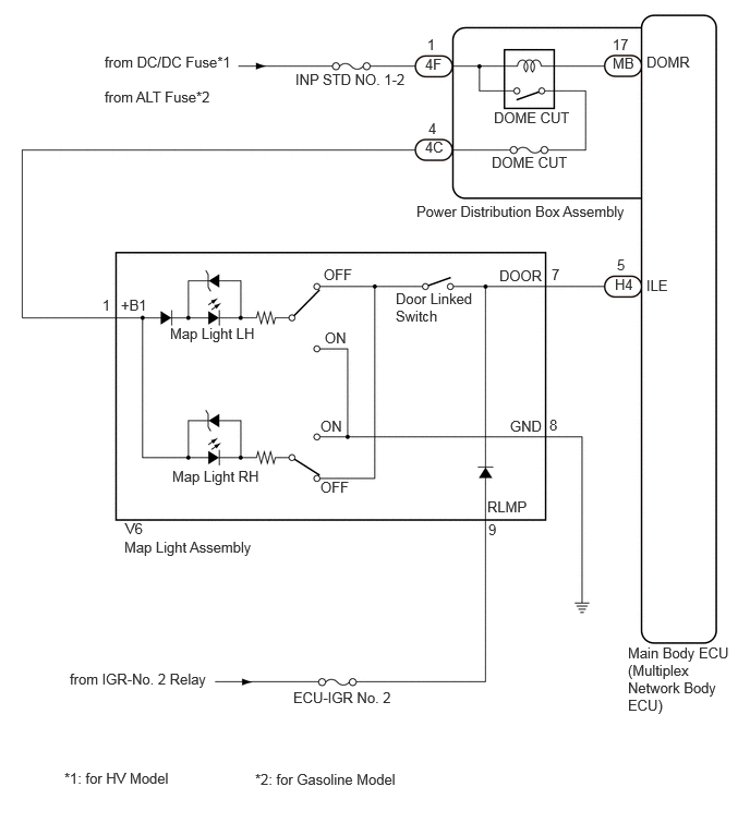
w/o Room Light


E450710E01
1,0.51 2.375,0.823 1.375,0.313 10 false from DC/DC Fuse*1 4.063,0.531 4.375,0.729 0.313,0.198 10 false 4F 4.083,0.344 4.396,0.542 0.313,0.198 10 false 1 4.063,1.323 4.375,1.521 0.313,0.198 10 false 4C 4.094,1.146 4.406,1.344 0.313,0.198 10 false 4 2.823,0.677 3.99,0.938 1.167,0.26 10 false INP STD NO. 1-2 4.719,1.042 5.948,1.24 1.229,0.198 10 false DOME CUT 5.854,0.344 6.167,0.542 0.313,0.198 10 false 17 5.896,2.448 6.052,2.646 0.156,0.198 10 false 5 6.177,2.646 6.635,2.844 0.458,0.198 10 false ILE 6.177,0.51 6.792,0.708 0.615,0.198 10 false DOMR 3.979,1.938 7,2.198 3.021,0.26 10 false Power Distribution Box Assembly 4.771,2.552 5.385,2.75 0.615,0.198 10 false DOOR 4.875,3.99 5.333,4.188 0.458,0.198 10 false GND 5.25,3.979 5.563,4.177 0.313,0.198 10 false 8 5.271,2.542 5.427,2.74 0.156,0.198 10 false 7 3.781,2.771 4.552,3.188 0.771,0.417 10 false Door Linked Switch 4.656,4.76 5.271,4.958 0.615,0.198 10 false RLMP 4.667,4.979 4.823,5.177 0.156,0.198 10 false 9 3.063,4.573 3.521,4.771 0.458,0.198 10 false OFF 3.094,2.542 3.552,2.74 0.458,0.198 10 false OFF 3.104,3.146 3.417,3.344 0.313,0.198 10 false ON 3.063,3.99 3.375,4.188 0.313,0.198 10 false ON 1.625,3.104 2.854,3.302 1.229,0.198 10 false Map Light LH 1.646,4.469 2.875,4.667 1.229,0.198 10 false Map Light RH 1.156,2.833 1.615,3.031 0.458,0.198 10 false +B1 0.979,2.833 1.292,3.031 0.313,0.198 10 false 1 1.198,4.969 1.51,5.167 0.313,0.198 10 false V6 1.188,5.146 2.813,5.427 1.625,0.281 10 false Map Light Assembly 2.802,6.583 4.052,6.813 1.25,0.229 10 false ECU-IGR No. 2 0.667,6.406 2.333,6.646 1.667,0.24 10 false from IGR-No. 2 Relay 0.615,7.354 4.438,7.552 3.823,0.198 10 false *1: for HV Model 5.854,0.521 6.167,0.719 0.313,0.198 10 false MB 6,6.156 7,6.927 1,0.771 10 false Main Body ECU (Multiplex Network Body ECU) 5.875,2.635 6.125,2.906 0.25,0.271 10 false H4 4.698,1.469 5.927,1.667 1.229,0.198 10 false DOME CUT 1,0.844 2.375,1.156 1.375,0.313 10 false from ALT Fuse*2 2.438,7.365 6.26,7.563 3.823,0.198 10 false *2: for Gasoline Model

CAUTION / NOTICE / HINT

NOTICE:
·

Inspect the fuses for circuits related to this system before performing the following procedure.

·

Before replacing the main body ECU (multiplex network body ECU), refer to Service Bulletin.*1

*1: w/ Entry and Start System


HINT:

The DOME CUT relay supplies power to the interior lights. If all the lights that use power from the DOME CUT relay do not turn on, check the interior light auto cut circuit first.

Click hereVehicle Interior>LIGHTING (INT)>LIGHTING SYSTEM>Interior Light Auto Cut Circuit


PROCEDURE

1.PERFORM ACTIVE TEST USING GTS
a.

Perform the Active Test according to the display on the GTS.

Body Electrical > Main Body > Active Test
Tester Display Measurement Item Control Range Diagnostic Note
Illuminated Entry System Turns on the lights that are controlled by the illuminated entry system*1 OFF or ON Perform the Active Test with DOOR switch in the map light assembly and room light assembly*2 turned on.

*1: Refer to System Description for the lights that are controlled by the illuminated entry system.

Click hereVehicle Interior>LIGHTING (INT)>LIGHTING SYSTEM>SYSTEM DESCRIPTION

*2: w/ Room Light


Body Electrical > Main Body > Data List
Tester Display
Illuminated Entry System
50003 449 3020
OK:

All lights that are controlled by the illuminated entry system come on.


Result:
Result Proceed to
OK A
NG (Map light does not come on) B
NG (Room light*2 does not come on) C
NG (Map light and room light*2 does not come on) D


A

PROCEED TO NEXT SUSPECTED AREA SHOWN IN PROBLEM SYMPTOMS TABLE

B

2.INSPECT MAP LIGHT ASSEMBLY

C

4.CHECK HARNESS AND CONNECTOR (MAP LIGHT ASSEMBLY - ROOM LIGHT ASSEMBLY)

D

5.INSPECT MAP LIGHT ASSEMBLY
2.INSPECT MAP LIGHT ASSEMBLY

OK

3.CHECK HARNESS AND CONNECTOR (MAP LIGHT ASSEMBLY - POWER DISTRIBUTION BOX ASSEMBLY)

NG

REPLACE MAP LIGHT ASSEMBLY

3.CHECK HARNESS AND CONNECTOR (MAP LIGHT ASSEMBLY - POWER DISTRIBUTION BOX ASSEMBLY)
a.

Disconnect the 4C power distribution box assembly connector.


b.

Disconnect the H4 main body ECU (multiplex network body ECU) connector.*1

*1: w/o Room Light


c.

Measure the resistance according to the value(s) in the table below.

Standard Resistance (w/ Room Light):
Tester Connection Condition Specified Condition
V7-1(+B1) - 4C-4 Always Below 1 Ω


Standard Resistance (w/o Room Light):
Tester Connection Condition Specified Condition
V6-1 (+B1) - 4C-4 Always Below 1 Ω
V6-7 (DOOR) - H4-5 (ILE) Always Below 1 Ω
V6-8 (GND) - Body ground Always Below 1 Ω
V6-1 (+B1) or 4C-4 - Body ground Always 10 kΩ or higher
V6-7 (DOOR) or H4-5 (ILE) - Body ground Always 10 kΩ or higher


Result:
Proceed to
OK
NG


OK

NG

REPAIR OR REPLACE HARNESS OR CONNECTOR

4.CHECK HARNESS AND CONNECTOR (MAP LIGHT ASSEMBLY - ROOM LIGHT ASSEMBLY)
a.

Disconnect the 4C power distribution box assembly connector.


b.

Disconnect the V3 room light assembly connector.


c.

Disconnect the V7 map light assembly connector.


d.

Measure the resistance according to the value(s) in the table below.

Standard Resistance:
Tester Connection Condition Specified Condition
V3-1 (B) - V7-1 (+B1) Always Below 1 Ω
V3-3 (CTY) - V7-9 (RLMP) Always Below 1 Ω


Result:
Proceed to
OK
NG


OK

NG

REPAIR OR REPLACE HARNESS OR CONNECTOR

5.INSPECT MAP LIGHT ASSEMBLY

OK

6.CHECK HARNESS AND CONNECTOR (MAP LIGHT ASSEMBLY - POWER DISTRIBUTION BOX ASSEMBLY)

NG

REPLACE MAP LIGHT ASSEMBLY

6.CHECK HARNESS AND CONNECTOR (MAP LIGHT ASSEMBLY - POWER DISTRIBUTION BOX ASSEMBLY)
a.

Disconnect the 4C power distribution box assembly connector.


b.

Disconnect the H4 main body ECU (multiplex network body ECU) connector.


c.

Measure the resistance according to the value(s) in the table below.

Standard Resistance:
Tester Connection Condition Specified Condition
V7-1(+B1) - 4C-4 Always Below 1 Ω
V7-2 (DOOR) - H4-5 (ILE) Always Below 1 Ω
V7-1(+B1) or 4C-4 - Body ground Always 10 kΩ or higher
V7-2 (DOOR) or H4-5 (ILE) - Body ground Always 10 kΩ or higher


Result:
Proceed to
OK
NG


OK

NG

REPAIR OR REPLACE HARNESS OR CONNECTOR