C551 MANUAL TRANSMISSION / TRANSAXLE OUTPUT SHAFT REASSEMBLY
PROCEDURE

 33321N
1.INSTALL FRONT OUTPUT SHAFT BEARING
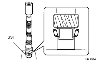
Using SST and a press, install the front output shaft bearing onto the output shaft.
- SST
- 09710-22021 (09710-01051)
33335C
2.INSTALL 1ST GEAR NEEDLE ROLLER BEARING
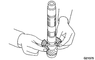
Coat the 1st gear needle roller bearing with gear oil and install it to the output shaft.
33335
3.INSTALL 1ST GEAR
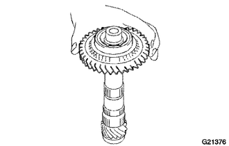
Coat the 1st gear with gear oil and install it to the output shaft.
33037B
4.INSTALL 1ST GEAR SYNCHRONIZER RING
Coat the 1st gear synchronizer ring with gear oil and install it to the 1st gear.
33361
5.INSTALL NO. 1 TRANSMISSION CLUTCH HUB
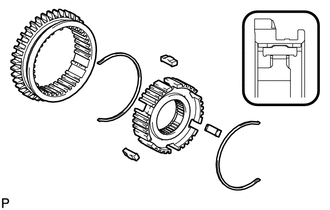
Install the reverse gear to the No. 1 transmission clutch hub and then install the 3 No. 1 clutch hub shifting keys and 2 No. 1 clutch hub shifting key springs.
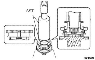
Using SST and a press, install the No. 1 transmission clutch hub set to the output shaft.
- SST
- 09316-60011 (09316-00011, 09316-00071)
- NOTICE:
-
Install the No. 1 transmission clutch hub set in the correct orientation shown in the illustration.
33361B
6.INSTALL NO. 1 CLUTCH HUB SHAFT SNAP RING
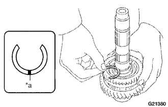
| *a | Alignment Mark |
Select a No. 1 clutch hub shaft snap ring that allows the minimum axial play.
- Standard clearance:
0 to 0.1 mm (0 to 0.0039 in.)
- Snap Ring Thickness:
Part No. Mark Thickness
mm (in.)90520-32014 A 2.280 (0.0898) 90520-32015 B 2.340 (0.0921) 90520-32016 C 2.400 (0.0945) 90520-32017 D 2.460 (0.0969) 90520-32018 E 2.520 (0.0992) 90520-32019 F 2.580 (0.1016)
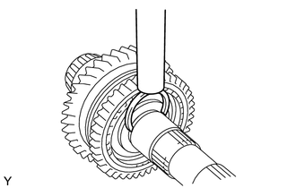
Using a brass bar and hammer, install the No. 1 clutch hub shaft snap ring to the output shaft.
Inspect the 1st gear thrust clearance and radial clearance (See page Drivetrain>C551 (MANUAL TRANSMISSION / TRANSAXLE)>OUTPUT SHAFT>DISASSEMBLY).
If either clearance is more than the maximum, check the installation condition of the No. 1 transmission clutch hub and repeat the procedure to select a No. 1 clutch hub shaft snap ring.
33332C
7.INSTALL 2ND GEAR BEARING SPACER
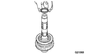
Coat the 2nd gear bearing spacer with gear oil and install it to the output shaft.
33332B
8.INSTALL 2ND GEAR NEEDLE ROLLER BEARING
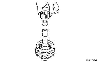
Coat the 2nd gear needle roller bearing with gear oil and install it to the output shaft.
33038E
9.INSTALL 2ND SYNCHRONIZER RING
Coat the 2nd synchronizer ring with gear oil, and install it to the reverse gear.
33332
10.INSTALL 2ND GEAR
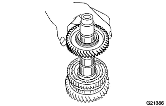
Coat the 2nd gear with gear oil and install it to the output shaft.
33423A
11.INSTALL 3RD DRIVEN GEAR
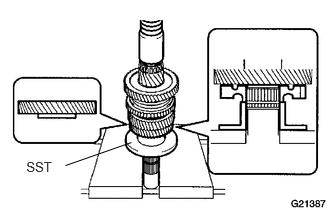
Using SST and a press, install the 3rd driven gear to the output shaft.
- SST
- 09316-60011 (09316-00041)
- NOTICE:
-
Install the 3rd driven gear while making sure that the cutout of the 2nd gear synchronizer ring and the No. 1 clutch hub shifting key are aligned.
Inspect the 2nd gear thrust clearance and radial clearance (See page Drivetrain>C551 (MANUAL TRANSMISSION / TRANSAXLE)>OUTPUT SHAFT>DISASSEMBLY).
If the clearance is more than the maximum, check the installation condition of the 3rd gear.
33431B
12.INSTALL OUTPUT SHAFT SPACER
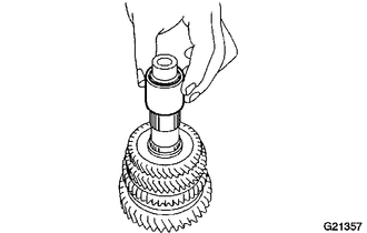
Install the output shaft spacer to the output shaft.
33422B
13.INSTALL 4TH DRIVEN GEAR
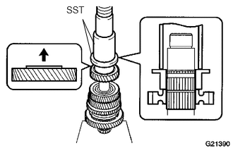
Using SST and a press, install the 4th driven gear to the output shaft.
- SST
- 09223-00010
09316-60011 (09316-00021)
33428C
14.INSTALL 5TH DRIVEN GEAR
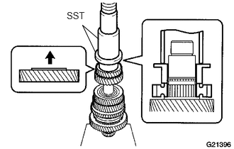
Using SST and a press, install the 5th driven gear to the output shaft.
- SST
- 09223-00010
09316-60011 (09316-00021)
33428A
15.INSTALL COUNTER 5TH GEAR SHAFT SNAP RING
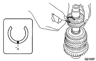
Using the table below, select a new counter 5th gear shaft snap ring that makes the thrust clearance of the counter 5th driven gear less than 0.1 mm (0.00394 in.).
| *a | Alignment Mark |
- Snap Ring Thickness:
Part No. Mark Thickness
mm (in.)90520-27070 A 2.220 (0.0874) 90520-27071 B 2.280 (0.0898) 90520-27072 C 2.340 (0.0921) 90520-27073 D 2.400 (0.0945) 90520-27074 E 2.460 (0.0969) 90520-27075 F 2.520 (0.0992) 90520-27076 G 2.580 (0.1016) 90520-27077 H 2.640 (0.1039) 90520-27078 J 2.700 (0.1063)
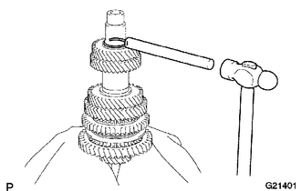
Using a brass bar and hammer, install the counter 5th gear shaft snap ring to the output shaft.
33321A
16.INSTALL REAR OUTPUT SHAFT BEARING
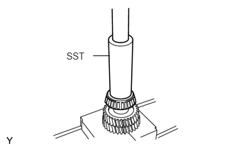
Using SST and a press, install the rear output shaft bearing onto the output shaft.
- SST
- 09612-22011