P910 HYBRID TRANSMISSION / TRANSAXLE HYBRID TRANSAXLE SYSTEM ON-VEHICLE INSPECTION
CAUTION / NOTICE / HINT
- CAUTION:
-
-
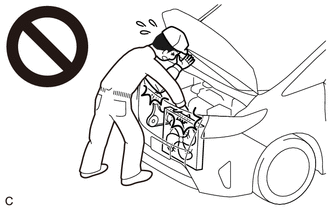
To prevent injury due to contact with an operating V-ribbed belt or cooling fan, keep your hands and clothing away from the V-ribbed belt and cooling fans when working in the engine compartment with the engine running or the ignition switch ON.
PROCEDURE

 51451A
1.REMOVE CENTER ENGINE UNDER COVER (w/ Cover)
51442C
2.REMOVE ENGINE UNDER COVER LH
3.INSPECT TRANSAXLE FLUID PRESSURE
- NOTICE:
-
Make sure to perform the following inspection after inspecting and adjusting the engine.
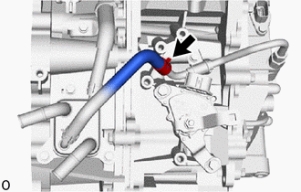
Slide the clip and disconnect the No. 1 motor cooling hose from the No. 1 motor cooling pipe.
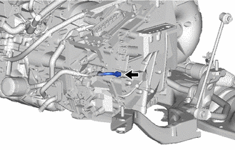
Loosen the flare nut of the No. 1 motor cooling pipe and disconnect the No. 1 motor cooling pipe from the union.
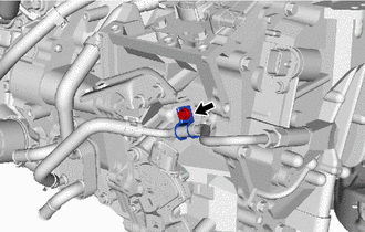
Remove the bolt and No. 1 oil cooler tube clamp from the hose bracket.
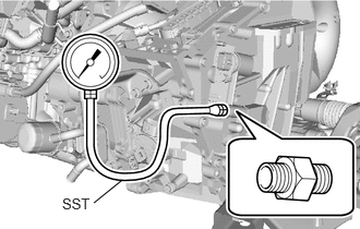
Install SST to the union.
- SST
- 09993-19015 (09993-00020, 09993-00030)
Put the engine in Inspection Mode (Maintenance Mode).
Click hereGeneral>INTRODUCTION>REPAIR INSTRUCTION>INSPECTION MODE PROCEDURE
Measure the hybrid transaxle fluid pressure.
- Reference:
Maintenance Mode Engine Idle Speed Hybrid Transaxle Fluid Temperature Hybrid Transaxle Fluid Pressure 950 to 1050 rpm 20 to 50°C (68 to 122°F) 9.8 kPa (0.1 kgf/cm2, 1 psi) or more
- NOTICE:
-
Be sure to cancel maintenance mode immediately after the hybrid transaxle fluid pressure check is completed.
Remove SST from the union.
Temporarily connect a new No. 1 motor cooling pipe to the union with the flare nut.
Install the No. 2 oil cooler tube clamp to the No. 1 transmission control cable bracket with the bolt.
- Torque:
- 8.0 N*m (82 kgf*cm, 71 in.*lbf)
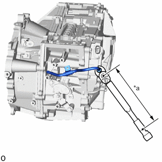
| *a | Torque Wrench Fulcrum Length |
Using a 17 mm union nut wrench, tighten the flare nut to connect the No. 1 motor cooling pipe.
- Torque:
- Specified Tightening Torque : 34.3 N*m (350 kgf*cm, 25 ft.*lbf)
- HINT:
- ·
Calculate the torque wrench reading when changing the fulcrum length of the torque wrench.
Click hereGeneral>INTRODUCTION>REPAIR INSTRUCTION>PRECAUTION
·When using a 17 mm union nut wrench (fulcrum length of 30 mm (1.18 in.)) + torque wrench (fulcrum length of 180 mm (7.09 in.)): 29.4 N*m (300 kgf*cm, 22 ft.*lbf)
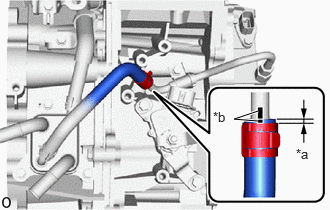
| *a | 2 to 7 mm (0.0787 to 0.276 in.) |
| *b | Paint Mark |
Connect the No. 1 motor cooling hose to the No. 1 motor cooling pipe and slide the clip to secure it.
- NOTICE:
-
Make sure to align the paint mark on the No. 1 motor cooling pipe with the paint mark on the No. 1 motor cooling hose.
51442C
4.INSTALL ENGINE UNDER COVER LH
51451A
5.INSTALL CENTER ENGINE UNDER COVER (w/ Cover)