Home › Audio / Visual / Telematics › NAVIGATION / MULTI INFO DISPLAY › NAVIGATION SYSTEM › 2020.07–2020.09
RM36W0E _56 Audio / Visual / Telematics _088616 NAVIGATION / MULTI INFO DISPLAY _0422142 NAVIGATION SYSTEM J

NAVIGATION / MULTI INFO DISPLAY  NAVIGATION SYSTEM  Speaker Circuit  


DESCRIPTION

If there is a short in a speaker circuit, the radio and display receiver assembly detects it and stops output to the speakers.

Thus sound cannot be heard from the speakers even if there is no malfunction in the radio and display receiver assembly or speakers.


WIRING DIAGRAM
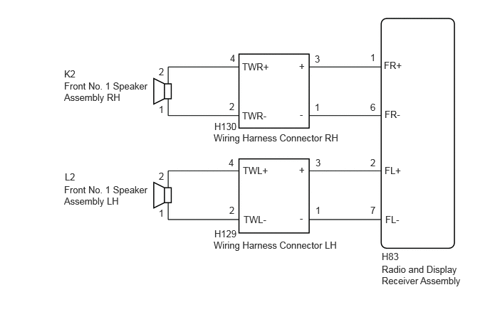
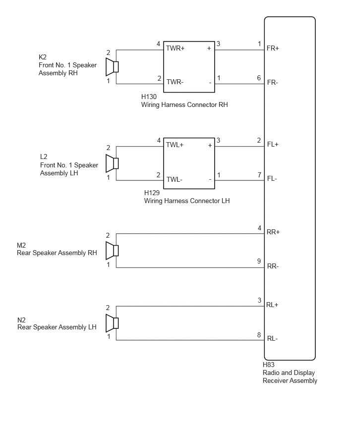
for 2 Speakers
E439263E01
3.135,1.771 3.75,1.969 0.615,0.198 10 false H130 3.125,1.938 5.115,2.229 1.99,0.292 10 false Wiring Harness Connector RH 3.135,3.344 3.75,3.542 0.615,0.198 10 false H129 3.125,3.51 5.115,3.802 1.99,0.292 10 false Wiring Harness Connector LH 5.583,3.865 6.781,4.344 1.198,0.479 10 false Radio and Display Receiver Assembly 5.583,3.677 6.198,3.875 0.615,0.198 10 false H83 5.615,0.875 6.229,1.073 0.615,0.198 10 false FR+ 5.625,1.594 6.24,1.792 0.615,0.198 10 false FR- 5.635,3.135 6.25,3.333 0.615,0.198 10 false FL- 5.625,2.417 6.24,2.615 0.615,0.198 10 false FL+ 3.542,0.896 4.156,1.094 0.615,0.198 10 false TWR+ 3.542,1.615 4.156,1.813 0.615,0.198 10 false TWR- 3.552,2.417 4.167,2.615 0.615,0.198 10 false TWL+ 3.563,3.135 4.177,3.333 0.615,0.198 10 false TWL- 0.938,1.177 2.208,1.688 1.271,0.51 10 false Front No. 1 Speaker Assembly RH 0.938,2.698 2.208,3.208 1.271,0.51 10 false Front No. 1 Speaker Assembly LH 0.938,1 1.552,1.198 0.615,0.198 10 false K2 0.948,2.51 1.563,2.708 0.615,0.198 10 false L2 2.323,0.969 2.573,1.177 0.25,0.208 10 false 2 2.323,1.521 2.573,1.729 0.25,0.208 10 false 1 2.323,2.5 2.573,2.708 0.25,0.208 10 false 2 2.323,3.042 2.573,3.25 0.25,0.208 10 false 1 3.354,1.479 3.604,1.688 0.25,0.208 10 false 2 3.354,3 3.604,3.208 0.25,0.208 10 false 2 3.365,0.771 3.615,0.979 0.25,0.208 10 false 4 3.344,2.302 3.594,2.51 0.25,0.208 10 false 4 4.615,2.302 4.865,2.51 0.25,0.208 10 false 3 4.604,0.781 4.854,0.99 0.25,0.208 10 false 3 4.615,3 4.865,3.208 0.25,0.208 10 false 1 4.604,1.49 4.854,1.698 0.25,0.208 10 false 1 5.417,0.76 5.667,0.969 0.25,0.208 10 false 1 5.417,1.49 5.667,1.698 0.25,0.208 10 false 6 5.417,2.302 5.667,2.51 0.25,0.208 10 false 2 5.417,3 5.667,3.208 0.25,0.208 10 false 7 4.375,0.885 4.667,1.094 0.292,0.208 10 false + 4.385,1.594 4.677,1.802 0.292,0.208 10 false - 4.375,2.406 4.667,2.615 0.292,0.208 10 false + 4.385,3.115 4.677,3.323 0.292,0.208 10 false -

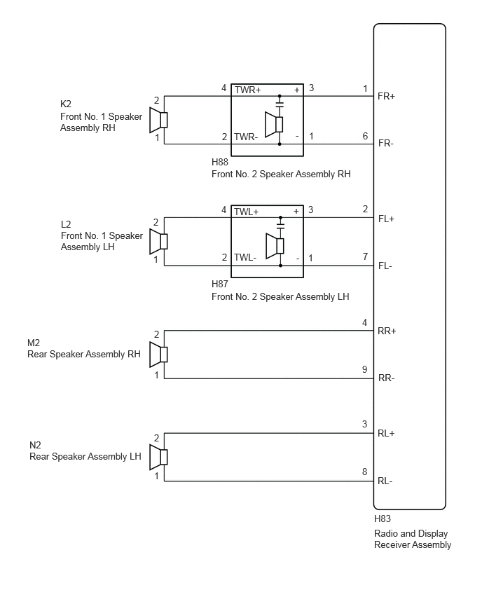
for 4 Speakers
E445951E01
0.813,1.115 1.125,1.313 0.313,0.198 10 false K2 0.813,1.281 2.104,1.646 1.292,0.365 10 false Front No. 1 Speaker Assembly RH 2.24,1.021 2.552,1.219 0.313,0.198 10 false 2 2.24,1.615 2.552,1.813 0.313,0.198 10 false 1 3.292,0.833 3.604,1.031 0.313,0.198 10 false 4 3.313,1.563 3.625,1.76 0.313,0.198 10 false 2 4.563,1.552 4.875,1.75 0.313,0.198 10 false 1 4.552,0.833 4.865,1.031 0.313,0.198 10 false 3 3.49,0.927 4.094,1.156 0.604,0.229 10 false TWR+ 3.5,1.635 4.104,1.865 0.604,0.229 10 false TWR- 5.417,0.833 5.729,1.031 0.313,0.198 10 false 1 5.406,1.552 5.719,1.75 0.313,0.198 10 false 6 5.604,0.927 6.208,1.156 0.604,0.229 10 false FR+ 5.615,1.646 6.219,1.875 0.604,0.229 10 false FR- 2.969,1.948 3.573,2.177 0.604,0.229 10 false H130 2.969,2.115 5,2.365 2.031,0.25 10 false Wiring Harness Connector RH 0.844,3.208 1.156,3.406 0.313,0.198 10 false L2 0.844,3.385 2.135,3.75 1.292,0.365 10 false Front No. 1 Speaker Assembly LH 2.24,3.021 2.552,3.219 0.313,0.198 10 false 2 2.24,3.646 2.552,3.844 0.313,0.198 10 false 1 3.292,3.594 3.604,3.792 0.313,0.198 10 false 2 3.302,2.865 3.615,3.063 0.313,0.198 10 false 4 4.552,2.865 4.865,3.063 0.313,0.198 10 false 3 4.563,3.594 4.875,3.792 0.313,0.198 10 false 1 5.406,2.865 5.719,3.063 0.313,0.198 10 false 2 5.417,3.594 5.729,3.792 0.313,0.198 10 false 7 3.49,2.958 4.094,3.188 0.604,0.229 10 false TWL+ 3.5,3.688 4.104,3.917 0.604,0.229 10 false TWL- 4.354,0.927 4.667,1.125 0.313,0.198 10 false + 4.396,1.646 4.708,1.844 0.313,0.198 10 false - 4.375,2.969 4.688,3.167 0.313,0.198 10 false + 4.396,3.677 4.708,3.875 0.313,0.198 10 false - 3.031,3.969 3.635,4.198 0.604,0.229 10 false H129 3.031,4.135 5.063,4.385 2.031,0.25 10 false Wiring Harness Connector LH 5.615,2.948 6.219,3.177 0.604,0.229 10 false FL+ 5.615,3.667 6.219,3.896 0.604,0.229 10 false FL- 0.354,5.073 0.667,5.271 0.313,0.198 10 false M2 0.354,5.229 2.583,5.469 2.229,0.24 10 false Rear Speaker Assembly RH 2.24,5.479 2.552,5.677 0.313,0.198 10 false 1 2.229,4.865 2.542,5.063 0.313,0.198 10 false 2 5.417,4.708 5.74,4.958 0.323,0.25 10 false 4 5.406,5.406 5.729,5.656 0.323,0.25 10 false 9 5.604,4.792 6.208,5.021 0.604,0.229 10 false RR+ 5.615,5.51 6.219,5.74 0.604,0.229 10 false RR- 0.365,6.646 0.677,6.844 0.313,0.198 10 false N2 0.365,6.792 2.594,7.031 2.229,0.24 10 false Rear Speaker Assembly LH 2.229,6.385 2.542,6.583 0.313,0.198 10 false 2 2.25,6.99 2.563,7.188 0.313,0.198 10 false 1 5.417,6.229 5.74,6.479 0.323,0.25 10 false 3 5.406,6.958 5.729,7.208 0.323,0.25 10 false 8 5.594,6.323 6.198,6.552 0.604,0.229 10 false RL+ 5.615,7.031 6.219,7.26 0.604,0.229 10 false RL- 5.521,7.583 6.125,7.813 0.604,0.229 10 false H83 5.521,7.75 6.76,8.125 1.24,0.375 10 false Radio and Display Receiver Assembly

for 6 Speakers
E437700E01
5.563,7.844 6.823,8.323 1.26,0.479 10 false Radio and Display Receiver Assembly 5.615,1.344 6.073,1.542 0.458,0.198 10 false FR+ 5.625,2.042 6.083,2.24 0.458,0.198 10 false FR- 5.625,3.865 6.083,4.063 0.458,0.198 10 false FL- 5.625,3.167 6.083,3.365 0.458,0.198 10 false FL+ 5.615,4.833 6.073,5.031 0.458,0.198 10 false RR+ 5.625,5.531 6.083,5.729 0.458,0.198 10 false RR- 5.615,6.354 6.073,6.552 0.458,0.198 10 false RL+ 5.615,7.063 6.073,7.26 0.458,0.198 10 false RL- 5.563,7.625 6.021,7.823 0.458,0.198 10 false H83 5.385,6.927 5.604,7.125 0.219,0.198 10 false 8 5.385,6.219 5.604,6.417 0.219,0.198 10 false 3 5.385,5.406 5.604,5.604 0.219,0.198 10 false 9 5.385,4.708 5.604,4.906 0.219,0.198 10 false 4 2.292,4.885 2.51,5.083 0.219,0.198 10 false 2 2.292,5.49 2.51,5.688 0.219,0.198 10 false 1 2.292,6.427 2.51,6.625 0.219,0.198 10 false 2 2.292,6.99 2.51,7.188 0.219,0.198 10 false 1 2.281,3.219 2.5,3.417 0.219,0.198 10 false 2 2.281,3.771 2.5,3.969 0.219,0.198 10 false 1 3.292,3.031 3.51,3.229 0.219,0.198 10 false 4 3.302,3.74 3.521,3.938 0.219,0.198 10 false 2 4.583,3.031 4.802,3.229 0.219,0.198 10 false 3 4.583,3.75 4.802,3.948 0.219,0.198 10 false 1 5.396,3.021 5.615,3.219 0.219,0.198 10 false 2 5.396,3.729 5.615,3.927 0.219,0.198 10 false 7 3.479,3.063 3.938,3.26 0.458,0.198 10 false TWL+ 3.479,3.74 3.938,3.938 0.458,0.198 10 false TWL- 3.49,1.25 3.948,1.448 0.458,0.198 10 false TWR+ 3.479,1.948 3.938,2.146 0.458,0.198 10 false TWR- 3.292,1.219 3.51,1.417 0.219,0.198 10 false 4 3.302,1.948 3.521,2.146 0.219,0.198 10 false 2 4.594,1.219 4.813,1.417 0.219,0.198 10 false 3 4.594,1.938 4.813,2.135 0.219,0.198 10 false 1 4.375,1.25 4.594,1.448 0.219,0.198 10 false + 4.365,3.052 4.583,3.25 0.219,0.198 10 false + 4.396,1.927 4.615,2.125 0.219,0.198 10 false - 4.406,3.75 4.625,3.948 0.219,0.198 10 false - 5.396,1.229 5.615,1.427 0.219,0.198 10 false 1 5.396,1.938 5.615,2.135 0.219,0.198 10 false 6 3.146,2.323 3.604,2.521 0.458,0.198 10 false H88 3.146,2.5 5.51,2.771 2.365,0.271 10 false Front No. 2 Speaker Assembly RH 3.146,4.135 3.604,4.333 0.458,0.198 10 false H87 3.146,4.323 5.51,4.594 2.365,0.271 10 false Front No. 2 Speaker Assembly LH 2.292,1.406 2.51,1.604 0.219,0.198 10 false 2 2.302,1.958 2.521,2.156 0.219,0.198 10 false 1 0.896,1.458 1.354,1.656 0.458,0.198 10 false K2 0.896,1.646 2.188,2.104 1.292,0.458 10 false Front No. 1 Speaker Assembly RH 0.906,3.417 2.198,3.875 1.292,0.458 10 false Front No. 1 Speaker Assembly LH 0.906,3.25 1.365,3.448 0.458,0.198 10 false L2 0.406,5.177 2.375,5.448 1.969,0.271 10 false Rear Speaker Assembly RH 0.438,6.698 2.406,6.969 1.969,0.271 10 false Rear Speaker Assembly LH 0.406,5.01 0.865,5.208 0.458,0.198 10 false M2 0.438,6.531 0.896,6.729 0.458,0.198 10 false N2

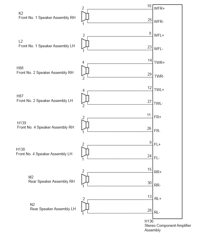
for 8 Speakers
E445952E05
0.677,0.396 0.99,0.594 0.313,0.198 10 false K2 0.677,0.552 5.417,0.75 4.74,0.198 10 false Front No. 1 Speaker Assembly RH 2.979,0.208 3.292,0.406 0.313,0.198 10 false 2 2.99,0.781 3.302,0.979 0.313,0.198 10 false 1 5.354,0.125 5.667,0.323 0.313,0.198 10 false 10 5.375,0.635 5.688,0.833 0.313,0.198 10 false 25 0.677,1.417 0.99,1.615 0.313,0.198 10 false L2 0.677,1.583 5.417,1.781 4.74,0.198 10 false Front No. 1 Speaker Assembly LH 0.604,2.385 0.917,2.583 0.313,0.198 10 false H88 0.604,2.552 5.344,2.75 4.74,0.198 10 false Front No. 2 Speaker Assembly RH 0.604,3.406 0.917,3.604 0.313,0.198 10 false H87 0.604,3.573 5.344,3.771 4.74,0.198 10 false Front No. 2 Speaker Assembly LH 0.625,4.385 1.115,4.656 0.49,0.271 10 false H139 0.625,4.542 5.365,4.74 4.74,0.198 10 false Front No. 4 Speaker Assembly RH 0.583,5.344 1.073,5.615 0.49,0.271 10 false H138 0.583,5.51 5.323,5.708 4.74,0.198 10 false Front No. 4 Speaker Assembly LH 1.031,6.354 1.521,6.625 0.49,0.271 10 false M2 1.031,6.51 5.771,6.708 4.74,0.198 10 false Rear Speaker Assembly RH 1.094,7.354 1.583,7.625 0.49,0.271 10 false N2 1.094,7.51 3.229,7.719 2.135,0.208 10 false Rear Speaker Assembly LH 3.01,1.198 3.323,1.396 0.313,0.198 10 false 2 3,1.76 3.313,1.958 0.313,0.198 10 false 1 2.99,2.177 3.302,2.375 0.313,0.198 10 false 4 3,2.76 3.313,2.958 0.313,0.198 10 false 2 3,3.198 3.313,3.396 0.313,0.198 10 false 4 3,3.76 3.313,3.958 0.313,0.198 10 false 2 3,4.188 3.313,4.385 0.313,0.198 10 false 2 2.99,5.156 3.302,5.354 0.313,0.198 10 false 2 2.99,6.135 3.302,6.333 0.313,0.198 10 false 2 3.01,7.146 3.323,7.344 0.313,0.198 10 false 2 2.99,4.719 3.302,4.917 0.313,0.198 10 false 1 2.979,5.708 3.292,5.906 0.313,0.198 10 false 1 2.99,6.688 3.302,6.885 0.313,0.198 10 false 1 2.979,7.688 3.292,7.885 0.313,0.198 10 false 1 5.427,1.125 5.74,1.323 0.313,0.198 10 false 8 5.365,1.625 5.677,1.823 0.313,0.198 10 false 23 5.375,2.104 5.688,2.302 0.313,0.198 10 false 14 5.365,2.615 5.677,2.813 0.313,0.198 10 false 29 5.365,3.104 5.677,3.302 0.313,0.198 10 false 12 5.365,3.604 5.677,3.802 0.313,0.198 10 false 27 5.344,4.094 5.656,4.292 0.313,0.198 10 false 11 5.354,4.583 5.667,4.781 0.313,0.198 10 false 26 5.438,5.094 5.75,5.292 0.313,0.198 10 false 9 5.365,5.583 5.677,5.781 0.313,0.198 10 false 24 5.365,6.073 5.677,6.271 0.313,0.198 10 false 15 5.365,6.563 5.677,6.76 0.313,0.198 10 false 30 5.365,7.063 5.677,7.26 0.313,0.198 10 false 13 5.365,7.563 5.677,7.76 0.313,0.198 10 false 28 5.26,7.958 5.823,8.135 0.563,0.177 10 false H136 5.26,8.115 7.094,8.5 1.833,0.385 10 false Stereo Component Amplifier Assembly 5.604,0.219 6.219,0.417 0.615,0.198 10 false WFR+ 5.604,0.698 6.219,0.896 0.615,0.198 10 false WFR- 5.604,1.198 6.219,1.396 0.615,0.198 10 false WFL+ 5.604,1.688 6.219,1.885 0.615,0.198 10 false WFL- 5.604,2.188 6.219,2.385 0.615,0.198 10 false TWR+ 5.615,2.688 6.229,2.885 0.615,0.198 10 false TWR- 5.604,3.177 6.219,3.375 0.615,0.198 10 false TWL+ 5.594,3.677 6.208,3.875 0.615,0.198 10 false TWL- 5.604,4.167 6.219,4.365 0.615,0.198 10 false FR+ 5.604,4.667 6.219,4.865 0.615,0.198 10 false FR- 5.604,5.167 6.219,5.365 0.615,0.198 10 false FL+ 5.604,5.656 6.219,5.854 0.615,0.198 10 false FL- 5.604,6.167 6.219,6.365 0.615,0.198 10 false RR+ 5.604,6.646 6.219,6.844 0.615,0.198 10 false RR- 5.615,7.135 6.229,7.333 0.615,0.198 10 false RL+ 5.604,7.635 6.219,7.833 0.615,0.198 10 false RL-

CAUTION / NOTICE / HINT

NOTICE:

Depending on the parts that are replaced during vehicle inspection or maintenance, performing initialization, registration or calibration may be needed. Refer to Precaution for Navigation System.

Click hereAudio / Visual / Telematics>NAVIGATION / MULTI INFO DISPLAY>NAVIGATION SYSTEM>PRECAUTION


PROCEDURE

1.CHECK MODEL
a.

Choose the model to be inspected.

Result:
Result Proceed to
for 2 Speakers A
for 4 Speakers B
for 6 Speakers C
for 8 Speakers D


A

2.CHECK HARNESS AND CONNECTOR (RADIO AND DISPLAY RECEIVER ASSEMBLY - FRONT NO. 1 SPEAKER ASSEMBLY - WIRING HARNESS CONNECTOR)

B

4.CHECK SPEAKER (OPERATION CHECK)

C

9.CHECK SPEAKER (OPERATION CHECK)

D

15.CHECK SPEAKER (OPERATION CHECK)
2.CHECK HARNESS AND CONNECTOR (RADIO AND DISPLAY RECEIVER ASSEMBLY - FRONT NO. 1 SPEAKER ASSEMBLY - WIRING HARNESS CONNECTOR)
a.

Disconnect the H83 radio and display receiver assembly connector.


b.

Disconnect the K2 and L2 front No. 1 speaker assembly connectors.


c.

Disconnect the H130 and H129 wiring harness connector connectors.


d.

Measure the resistance according to the value (s) in the table below.

Standard Resistance:
Tester Connection Condition Specified Condition
H83-1 (FR+) - H130-3 (+) Always Below 1 Ω
H83-6 (FR-) - H130-1 (-) Always Below 1 Ω
H83-2 (FL+) - H129-3 (+) Always Below 1 Ω
H83-7 (FL-) - H129-1 (-) Always Below 1 Ω
H130-4 (TWR+) - K2-2 Always Below 1 Ω
H130-2 (TWR-) - K2-1 Always Below 1 Ω
H129-4 (TWL+) - L2-2 Always Below 1 Ω
H129-2 (TWL-) - L2-1 Always Below 1 Ω
H83-1 (FR+) or H130-3 (+) - Body ground Always 10 kΩ or higher
H83-6 (FR-) or H130-1 (-) - Body ground Always 10 kΩ or higher
H83-2 (FL+) or H129-3 (+) - Body ground Always 10 kΩ or higher
H83-7 (FL-) or H129-1 (-) - Body ground Always 10 kΩ or higher
H130-4 (TWR+) or K2-2 - Body ground Always 10 kΩ or higher
H130-2 (TWR-) or K2-1 - Body ground Always 10 kΩ or higher
H129-4 (TWL+) or L2-2 - Body ground Always 10 kΩ or higher
H129-2 (TWL-) or L2-1 - Body ground Always 10 kΩ or higher


Result:
Proceed to
OK
NG


OK

3.INSPECTION FRONT NO. 1 SPEAKER ASSEMBLY

NG

REPAIR OR REPLACE HARNESS OR CONNECTOR

3.INSPECTION FRONT NO. 1 SPEAKER ASSEMBLY

Click hereAudio / Visual / Telematics>AUDIO / VIDEO>PILLAR SPEAKER>INSPECTION

OK:

Malfunction disappears.


Result:
Proceed to
OK
NG


OK

END

NG

PROCEED TO NEXT SUSPECTED AREA SHOWN IN PROBLEM SYMPTOMS TABLE

4.CHECK SPEAKER (OPERATION CHECK)
a.
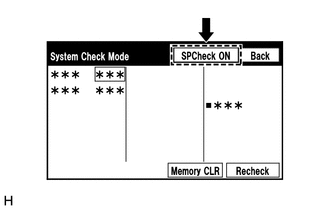
E268474

Enter the "System Check Mode" screen. Refer to Check Speaker in Operation Check.

Click hereAudio / Visual / Telematics>NAVIGATION / MULTI INFO DISPLAY>NAVIGATION SYSTEM>OPERATION CHECK


b.

Perform the operation check above and determine the speaker that is not operating.

Result:
Not Operating Speaker Proceed to
Front No. 1 speaker assembly A
Rear speaker assembly B


HINT:

If sound cannot be heard from any speaker, inspect all of them.


A

5.CHECK HARNESS AND CONNECTOR (RADIO AND DISPLAY RECEIVER ASSEMBLY - FRONT NO. 1 SPEAKER ASSEMBLY - WIRING HARNESS CONNECTOR)

B

7.CHECK HARNESS AND CONNECTOR (RADIO AND DISPLAY RECEIVER ASSEMBLY - REAR SPEAKER ASSEMBLY)
5.CHECK HARNESS AND CONNECTOR (RADIO AND DISPLAY RECEIVER ASSEMBLY - FRONT NO. 1 SPEAKER ASSEMBLY - WIRING HARNESS CONNECTOR)
a.

Disconnect the H83 radio and display receiver assembly connector.


b.

Disconnect the K2 and L2 front No. 1 speaker assembly connectors.


c.

Disconnect the H130 and H129 wiring harness connector connectors.


d.

Measure the resistance according to the value (s) in the table below.

Standard Resistance:
Tester Connection Condition Specified Condition
H83-1 (FR+) - H130-3 (+) Always Below 1 Ω
H83-6 (FR-) - H130-1 (-) Always Below 1 Ω
H83-2 (FL+) - H129-3 (+) Always Below 1 Ω
H83-7 (FL-) - H129-1 (-) Always Below 1 Ω
H130-4 (TWR+) - K2-2 Always Below 1 Ω
H130-2 (TWR-) - K2-1 Always Below 1 Ω
H129-4 (TWL+) - L2-2 Always Below 1 Ω
H129-2 (TWL-) - L2-1 Always Below 1 Ω
H83-1 (FR+) or H130-3 (+) - Body ground Always 10 kΩ or higher
H83-6 (FR-) or H130-1 (-) - Body ground Always 10 kΩ or higher
H83-2 (FL+) or H129-3 (+) - Body ground Always 10 kΩ or higher
H83-7 (FL-) or H129-1 (-) - Body ground Always 10 kΩ or higher
H130-4 (TWR+) or K2-2 - Body ground Always 10 kΩ or higher
H130-2 (TWR-) or K2-1 - Body ground Always 10 kΩ or higher
H129-4 (TWL+) or L2-2 - Body ground Always 10 kΩ or higher
H129-2 (TWL-) or L2-1 - Body ground Always 10 kΩ or higher


Result:
Proceed to
OK
NG


OK

6.INSPECTION FRONT NO. 1 SPEAKER ASSEMBLY

NG

REPAIR OR REPLACE HARNESS OR CONNECTOR

6.INSPECTION FRONT NO. 1 SPEAKER ASSEMBLY

Click hereAudio / Visual / Telematics>AUDIO / VIDEO>PILLAR SPEAKER>INSPECTION

OK:

Malfunction disappears.


Result:
Proceed to
OK
NG


OK

END

NG

PROCEED TO NEXT SUSPECTED AREA SHOWN IN PROBLEM SYMPTOMS TABLE

7.CHECK HARNESS AND CONNECTOR (RADIO AND DISPLAY RECEIVER ASSEMBLY - REAR SPEAKER ASSEMBLY)
a.

Disconnect the H83 radio and display receiver assembly connector.


b.

Disconnect the M2 and N2 rear speaker assembly connectors.


c.

Measure the resistance according to the value (s) in the table below.

Standard Resistance:
Tester Connection Condition Specified Condition
H83-4 (RR+) - M2-2 Always Below 1 Ω
H83-9 (RR-) - M2-1 Always Below 1 Ω
H83-3 (RL+) - N2-2 Always Below 1 Ω
H83-8 (RL-) - N2-1 Always Below 1 Ω
H83-4 (RR+) or M2-2 - Body ground Always 10 kΩ or higher
H83-9 (RR-) or M2-1 - Body ground Always 10 kΩ or higher
H83-3 (RL+) or N2-2 - Body ground Always 10 kΩ or higher
H83-8 (RL-) or N2-1 - Body ground Always 10 kΩ or higher


Result:
Proceed to
OK
NG


OK

8.INSPECTION REAR SPEAKER ASSEMBLY

NG

REPAIR OR REPLACE HARNESS OR CONNECTOR

8.INSPECTION REAR SPEAKER ASSEMBLY

Click hereAudio / Visual / Telematics>AUDIO / VIDEO>REAR DOOR SPEAKER>INSPECTION

OK:

Malfunction disappears.


Result:
Proceed to
OK
NG


OK

END

NG

PROCEED TO NEXT SUSPECTED AREA SHOWN IN PROBLEM SYMPTOMS TABLE

9.CHECK SPEAKER (OPERATION CHECK)
a.
E268474

Enter the "System Check Mode" screen. Refer to Check Speaker in Operation Check.

Click hereAudio / Visual / Telematics>NAVIGATION / MULTI INFO DISPLAY>NAVIGATION SYSTEM>OPERATION CHECK


b.

Perform the operation check above and determine the speaker that is not operating.

Result:
Not Operating Speaker Proceed to
Front No. 1 speaker assembly or front No. 2 speaker assembly A
Rear speaker assembly B


HINT:

If sound cannot be heard from any speaker, inspect all of them.


A

10.CHECK HARNESS AND CONNECTOR (RADIO AND DISPLAY RECEIVER ASSEMBLY - FRONT NO. 1 SPEAKER ASSEMBLY - FRONT NO. 2 SPEAKER ASSEMBLY)

B

13.CHECK HARNESS AND CONNECTOR (RADIO AND DISPLAY RECEIVER ASSEMBLY - REAR SPEAKER ASSEMBLY)
10.CHECK HARNESS AND CONNECTOR (RADIO AND DISPLAY RECEIVER ASSEMBLY - FRONT NO. 1 SPEAKER ASSEMBLY - FRONT NO. 2 SPEAKER ASSEMBLY)
a.

Disconnect the H83 radio and display receiver assembly connector.


b.

Disconnect the K2 and L2 front No. 1 speaker assembly connectors.


c.

Disconnect the H88 and H87 front No. 2 speaker assembly connectors.


d.

Measure the resistance according to the value (s) in the table below.

Standard Resistance:
Tester Connection Condition Specified Condition
H83-1 (FR+) - H88-3 (+) Always Below 1 Ω
H83-6 (FR-) - H88-1 (-) Always Below 1 Ω
H83-2 (FL+) - H87-3 (+) Always Below 1 Ω
H83-7 (FL-) - H87-1 (-) Always Below 1 Ω
H88-4 (TWR+) - K2-2 Always Below 1 Ω
H88-2 (TWR-) - K2-1 Always Below 1 Ω
H87-4 (TWL+) - L2-2 Always Below 1 Ω
H87-2 (TWL-) - L2-1 Always Below 1 Ω
H83-1 (FR+) or H88-3 (+) - Body ground Always 10 kΩ or higher
H83-6 (FR-) or H88-1 (-) - Body ground Always 10 kΩ or higher
H83-2 (FL+) or H87-3 (+) - Body ground Always 10 kΩ or higher
H83-7 (FL-) or H87-1 (-) - Body ground Always 10 kΩ or higher
H88-4 (TWR+) or K2-2 - Body ground Always 10 kΩ or higher
H88-2 (TWR-) or K2-1 - Body ground Always 10 kΩ or higher
H87-4 (TWL+) or L2-2 - Body ground Always 10 kΩ or higher
H87-2 (TWL-) or L2-1 - Body ground Always 10 kΩ or higher


Result:
Proceed to
OK
NG


OK

11.INSPECT FRONT NO. 1 SPEAKER ASSEMBLY

NG

REPAIR OR REPLACE HARNESS OR CONNECTOR

11.INSPECT FRONT NO. 1 SPEAKER ASSEMBLY

OK

12.INSPECTION FRONT NO. 2 SPEAKER ASSEMBLY

NG

REPLACE FRONT NO. 1 SPEAKER ASSEMBLY

12.INSPECTION FRONT NO. 2 SPEAKER ASSEMBLY

Click hereAudio / Visual / Telematics>AUDIO / VIDEO>PILLAR SPEAKER>INSPECTION

OK:

Malfunction disappears.


Result:
Proceed to
OK
NG


OK

END

NG

PROCEED TO NEXT SUSPECTED AREA SHOWN IN PROBLEM SYMPTOMS TABLE

13.CHECK HARNESS AND CONNECTOR (RADIO AND DISPLAY RECEIVER ASSEMBLY - REAR SPEAKER ASSEMBLY)
a.

Disconnect the H83 radio and display receiver assembly connector.


b.

Disconnect the M2 and N2 rear speaker assembly connectors.


c.

Measure the resistance according to the value (s) in the table below.

Standard Resistance:
Tester Connection Condition Specified Condition
H83-4 (RR+) - M2-2 Always Below 1 Ω
H83-9 (RR-) - M2-1 Always Below 1 Ω
H83-3 (RL+) - N2-2 Always Below 1 Ω
H83-8 (RL-) - N2-1 Always Below 1 Ω
H83-4 (RR+) or M2-2 - Body ground Always 10 kΩ or higher
H83-9 (RR-) or M2-1 - Body ground Always 10 kΩ or higher
H83-3 (RL+) or N2-2 - Body ground Always 10 kΩ or higher
H83-8 (RL-) or N2-1 - Body ground Always 10 kΩ or higher


Result:
Proceed to
OK
NG


OK

14.INSPECTION REAR SPEAKER ASSEMBLY

NG

REPAIR OR REPLACE HARNESS OR CONNECTOR

14.INSPECTION REAR SPEAKER ASSEMBLY

Click hereAudio / Visual / Telematics>AUDIO / VIDEO>REAR DOOR SPEAKER>INSPECTION

OK:

Malfunction disappears.


Result:
Proceed to
OK
NG


OK

END

NG

PROCEED TO NEXT SUSPECTED AREA SHOWN IN PROBLEM SYMPTOMS TABLE

15.CHECK SPEAKER (OPERATION CHECK)
a.
E268474

Enter the "System Check Mode" screen. Refer to Check Speaker in Operation Check.

Click hereAudio / Visual / Telematics>NAVIGATION / MULTI INFO DISPLAY>NAVIGATION SYSTEM>OPERATION CHECK


b.

Perform the operation check above and determine the speaker that is not operating.

Result:
Not Operating Speaker Proceed to
Front No. 1 speaker assembly A
Front No. 2 speaker assembly B
Front No. 4 speaker assembly C
Rear speaker assembly D


HINT:

If sound cannot be heard from any speaker, inspect all of them.


A

16.CHECK HARNESS AND CONNECTOR (STEREO COMPONENT AMPLIFIER ASSEMBLY - FRONT NO. 1 SPEAKER ASSEMBLY)

B

18.CHECK HARNESS AND CONNECTOR (STEREO COMPONENT AMPLIFIER ASSEMBLY - FRONT NO. 2 SPEAKER ASSEMBLY)

C

20.CHECK HARNESS AND CONNECTOR (STEREO COMPONENT AMPLIFIER ASSEMBLY - FRONT NO. 4 SPEAKER ASSEMBLY)

D

22.CHECK HARNESS AND CONNECTOR (STEREO COMPONENT AMPLIFIER ASSEMBLY - REAR SPEAKER ASSEMBLY)
16.CHECK HARNESS AND CONNECTOR (STEREO COMPONENT AMPLIFIER ASSEMBLY - FRONT NO. 1 SPEAKER ASSEMBLY)
a.

Disconnect the H136 stereo component amplifier assembly connector.


b.

Disconnect the K2 and L2 front No. 1 speaker assembly connectors.


c.

Measure the resistance according to the value (s) in the table below.

Standard Resistance:
Tester Connection Condition Specified Condition
H136-10 (WFR+) - K2-2 Always Below 1 Ω
H136-25 (WFR-) - K2-1 Always Below 1 Ω
H136-8 (WFL+) - L2-2 Always Below 1 Ω
H136-23 (WFL-) - L2-1 Always Below 1 Ω
H136-10 (WFR+) or K2-2 - Body ground Always 10 kΩ or higher
H136-25 (WFR-) or K2-1 - Body ground Always 10 kΩ or higher
H136-8 (WFL+) or L2-2 - Body ground Always 10 kΩ or higher
H136-23 (WFL-) or L2-1 - Body ground Always 10 kΩ or higher


Result:
Proceed to
OK
NG


OK

17.INSPECTION FRONT NO. 1 SPEAKER ASSEMBLY

NG

REPAIR OR REPLACE HARNESS OR CONNECTOR

17.INSPECTION FRONT NO. 1 SPEAKER ASSEMBLY

Click hereAudio / Visual / Telematics>AUDIO / VIDEO>PILLAR SPEAKER>INSPECTION

OK:

Malfunction disappears.


Result:
Proceed to
OK
NG


OK

END

NG

PROCEED TO NEXT SUSPECTED AREA SHOWN IN PROBLEM SYMPTOMS TABLE

18.CHECK HARNESS AND CONNECTOR (STEREO COMPONENT AMPLIFIER ASSEMBLY - FRONT NO. 2 SPEAKER ASSEMBLY)
a.

Disconnect the H136 stereo component amplifier assembly connector.


b.

Disconnect the H88 and H87 front No. 2 speaker assembly connectors.


c.

Measure the resistance according to the value (s) in the table below.

Standard Resistance:
Tester Connection Condition Specified Condition
H136-14 (TWR+) - H88-4 Always Below 1 Ω
H136-29 (TWR-) - H88-2 Always Below 1 Ω
H136-12 (TWL+) - H87-4 Always Below 1 Ω
H136-27 (TWL-) - H87-2 Always Below 1 Ω
H136-14 (TWR+) or H88-4 - Body ground Always 10 kΩ or higher
H136-29 (TWR-) or H88-2 - Body ground Always 10 kΩ or higher
H136-12 (TWL+) or H87-4 - Body ground Always 10 kΩ or higher
H136-27 (TWL-) or H87-2 - Body ground Always 10 kΩ or higher


Result:
Proceed to
OK
NG


OK

19.INSPECTION FRONT NO. 2 SPEAKER ASSEMBLY

NG

REPAIR OR REPLACE HARNESS OR CONNECTOR

19.INSPECTION FRONT NO. 2 SPEAKER ASSEMBLY

Click hereAudio / Visual / Telematics>AUDIO / VIDEO>PILLAR SPEAKER>INSPECTION

OK:

Malfunction disappears.


Result:
Proceed to
OK
NG


OK

END

NG

PROCEED TO NEXT SUSPECTED AREA SHOWN IN PROBLEM SYMPTOMS TABLE

20.CHECK HARNESS AND CONNECTOR (STEREO COMPONENT AMPLIFIER ASSEMBLY - FRONT NO. 4 SPEAKER ASSEMBLY)
a.

Disconnect the H136 stereo component amplifier assembly connector.


b.

Disconnect the H139 and H138 front No. 4 speaker assembly connectors.


c.

Measure the resistance according to the value (s) in the table below.

Standard Resistance:
Tester Connection Condition Specified Condition
H136-11 (FR+) - H139-2 Always Below 1 Ω
H136-26 (FR-) - H139-1 Always Below 1 Ω
H136-9 (FL+) - H138-2 Always Below 1 Ω
H136-24 (FL-) - H138-1 Always Below 1 Ω
H136-11 (FR+) or H139-2 - Body ground Always 10 kΩ or higher
H136-26 (FR-) or H139-1 - Body ground Always 10 kΩ or higher
H136-9 (FL+) or H138-2 - Body ground Always 10 kΩ or higher
H136-24 (FL-) or H138-1 - Body ground Always 10 kΩ or higher


Result:
Proceed to
OK
NG


OK

21.INSPECTION FRONT NO. 4 SPEAKER ASSEMBLY

NG

REPAIR OR REPLACE HARNESS OR CONNECTOR

21.INSPECTION FRONT NO. 4 SPEAKER ASSEMBLY

Click hereAudio / Visual / Telematics>AUDIO / VIDEO>INSTRUMENT PANEL SPEAKER>INSPECTION

OK:

Malfunction disappears.


Result:
Proceed to
OK
NG


OK

END

NG

PROCEED TO NEXT SUSPECTED AREA SHOWN IN PROBLEM SYMPTOMS TABLE

22.CHECK HARNESS AND CONNECTOR (STEREO COMPONENT AMPLIFIER ASSEMBLY - REAR SPEAKER ASSEMBLY)
a.

Disconnect the H136 stereo component amplifier assembly connector.


b.

Disconnect the M2 and N2 rear speaker assembly connectors.


c.

Measure the resistance according to the value (s) in the table below.

Standard Resistance:
Tester Connection Condition Specified Condition
H136-15 (RR+) - M2-2 Always Below 1 Ω
H136-30 (RR-) - M2-1 Always Below 1 Ω
H136-13 (RL+) - N2-2 Always Below 1 Ω
H136-28 (RL-) - N2-1 Always Below 1 Ω
H136-15 (RR+) or M2-2 - Body ground Always 10 kΩ or higher
H136-30 (RR-) or M2-1 - Body ground Always 10 kΩ or higher
H136-13 (RL+) or N2-2 - Body ground Always 10 kΩ or higher
H136-28 (RL-) or N2-1 - Body ground Always 10 kΩ or higher


Result:
Proceed to
OK
NG


OK

23.INSPECTION REAR SPEAKER ASSEMBLY

NG

REPAIR OR REPLACE HARNESS OR CONNECTOR

23.INSPECTION REAR SPEAKER ASSEMBLY

Click hereAudio / Visual / Telematics>AUDIO / VIDEO>REAR DOOR SPEAKER>INSPECTION

OK:

Malfunction disappears.


Result:
Proceed to
OK
NG


OK

END

NG

PROCEED TO NEXT SUSPECTED AREA SHOWN IN PROBLEM SYMPTOMS TABLE