Home › Brake › BRAKE CONTROL / DYNAMIC CONTROL SYSTEMS › ELECTRONICALLY CONTROLLED BRAKE SYSTEM (for HV Model TMMF Made) › 2020.07–2021.11
RM36W0E _54 Brake _088016 BRAKE CONTROL / DYNAMIC CONTROL SYSTEMS _0435240 ELECTRONICALLY CONTROLLED BRAKE SYSTEM(for HV Model TMMF Made) C

BRAKE CONTROL / DYNAMIC CONTROL SYSTEMS  ELECTRONICALLY CONTROLLED BRAKE SYSTEM(for HV Model TMMF Made)  C13BA1C  Electronic Brake Booster Motor "A" Current Sensor Circuit Voltage Out of Range  


DESCRIPTION

When the temperature sensor inside the electric brake booster (brake booster with master cylinder assembly) meets the detection conditions, this DTC is stored.

DTC No. Detection Item DTC Detection Condition Trouble Area DTC Output from
C13BA1C Electronic Brake Booster Motor "A" Current Sensor Circuit Voltage Out of Range Motor current sensor current abnormality is detected for 0.2 seconds or more. Electric brake booster (brake booster with master cylinder assembly) Brake Booster

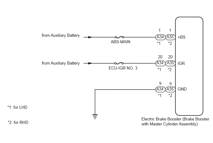
WIRING DIAGRAM

C443938E04
5.271,1.156 5.729,1.354 0.458,0.198 10 false A34 5.26,2.031 5.719,2.229 0.458,0.198 10 false A34 5.604,2.917 6.063,3.115 0.458,0.198 10 false A35 5.26,2.917 5.719,3.115 0.458,0.198 10 false A34 5.615,2.031 6.073,2.229 0.458,0.198 10 false A35 5.604,1.156 6.063,1.354 0.458,0.198 10 false A35 5.656,1.375 5.948,1.573 0.292,0.198 10 false *2 5.302,2.26 5.594,2.458 0.292,0.198 10 false *1 5.313,3.135 5.604,3.333 0.292,0.198 10 false *1 5.281,1.375 5.573,1.573 0.292,0.198 10 false *1 5.646,2.26 5.938,2.458 0.292,0.198 10 false *2 5.667,3.135 5.958,3.333 0.292,0.198 10 false *2 5.698,2.74 5.99,2.938 0.292,0.198 10 false 9 5.354,2.729 5.646,2.927 0.292,0.198 10 false 9 5.313,1.833 5.604,2.031 0.292,0.198 10 false 20 5.333,0.938 5.625,1.135 0.292,0.198 10 false 1 5.688,0.938 5.979,1.135 0.292,0.198 10 false 1 5.656,1.833 5.948,2.031 0.292,0.198 10 false 20 1.406,1.104 4.771,1.302 3.365,0.198 10 false from Auxiliary Battery 1.406,2.042 4.771,2.24 3.365,0.198 10 false from Auxiliary Battery 3.729,1.323 7.094,1.521 3.365,0.198 10 false ABS-MAIN 3.656,2.208 7.021,2.406 3.365,0.198 10 false ECU-IGR NO. 3 5.979,1.167 6.438,1.365 0.458,0.198 10 false +BS 5.979,2.052 6.438,2.25 0.458,0.198 10 false IGR 5.979,2.917 6.438,3.115 0.458,0.198 10 false GND 4.76,3.927 7.115,4.333 2.354,0.406 10 false Electric Brake Booster (Brake Booster with Master Cylinder Assembly) 0.25,3.531 1.938,3.729 1.688,0.198 10 false *1: for LHD 0.26,4.042 1.948,4.24 1.688,0.198 10 false *2: for RHD

CAUTION / NOTICE / HINT

NOTICE:
·

After replacing the electric brake booster (brake booster with master cylinder assembly), perform "Calibration" after performing "Reset Memory".

Click hereBrake>BRAKE CONTROL / DYNAMIC CONTROL SYSTEMS>ELECTRONICALLY CONTROLLED BRAKE SYSTEM (for HV Model TMMF Made)>UTILITY

·

Inspect the fuses for circuits related to this system before performing the following procedure.


PROCEDURE

1.CONFIRM MODEL
a.

Choose the model to be inspected


Result:
Result Proceed to
for LHD A
for RHD B


A

2.CHECK HARNESS AND CONNECTOR (POWER SOURCE TERMINAL)

B

3.CHECK HARNESS AND CONNECTOR (POWER SOURCE TERMINAL)
2.CHECK HARNESS AND CONNECTOR (POWER SOURCE TERMINAL)
a.

Make sure that there is no looseness at the locking part and the connecting part of the connectors.

OK:

The connector is securely connected.


b.

Disconnect the A34 electric brake booster (brake booster with master cylinder assembly) connector.


c.

Check both the connector case and the terminals for deformation and corrosion.

OK:

No deformation or corrosion.


d.

Measure the voltage according to the value(s) in the table below.

Standard Voltage:
Tester Connection Condition Specified Condition
A34-1 (+BS) - Body ground Always 11 to 14 V


Result:
Proceed to
OK
NG


OK

REPLACE BRAKE BOOSTER WITH MASTER CYLINDER ASSEMBLY

NG

REPAIR OR REPLACE HARNESS OR CONNECTOR

3.CHECK HARNESS AND CONNECTOR (POWER SOURCE TERMINAL)
a.

Make sure that there is no looseness at the locking part and the connecting part of the connectors.

OK:

The connector is securely connected.


b.

Disconnect the A35 electric brake booster (brake booster with master cylinder assembly) connector.


c.

Check both the connector case and the terminals for deformation and corrosion.

OK:

No deformation or corrosion.


d.

Measure the voltage according to the value(s) in the table below.

Standard Voltage:
Tester Connection Condition Specified Condition
A35-1 (+BS) - Body ground Always 11 to 14 V


Result:
Proceed to
OK
NG


OK

REPLACE BRAKE BOOSTER WITH MASTER CYLINDER ASSEMBLY

NG

REPAIR OR REPLACE HARNESS OR CONNECTOR