INTERIOR PANELS / TRIM ROOF HEADLINING REASSEMBLY
PROCEDURE

 86101J
1.INSTALL NO. 2 ANTENNA CORD SUB-ASSEMBLY (except Panoramic Moon Roof)
86101J
2.INSTALL NO. 2 ANTENNA CORD SUB-ASSEMBLY (for Panoramic Moon Roof)
82171
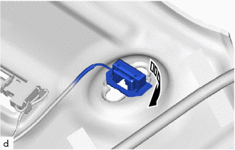
3.INSTALL NO. 1 ROOF WIRE (for TMMF Made)

|
Install in this Direction |
Turn the visor connectors approximately 90° clockwise to connect the visor connector as shown in the illustration.
- HINT:
-
Use the same procedures for the opposite side.
for Normal Roof:
Line up the No. 1 roof wire positioning tape and the roof headlining markings.
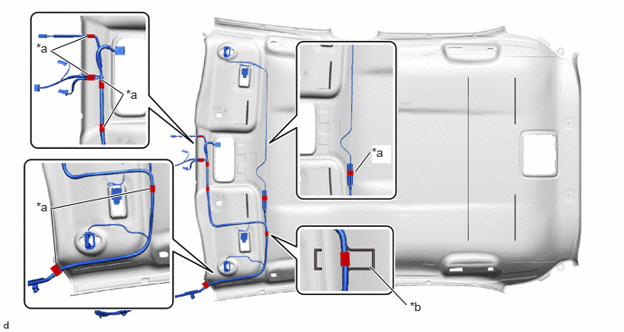
| *a | Positioning Tape | *b | Marking |
Install the No. 1 roof wire with 18 new pieces of adhesive tape.
- NOTICE:
- ·
Apply the tape securely in place.
·Do not touch the adhesive surface when applying the tape to prevent adhesion failure.
- HINT:
-
Adjust the slack of the No. 1 roof wire as shown in the adjustment area of illustration.
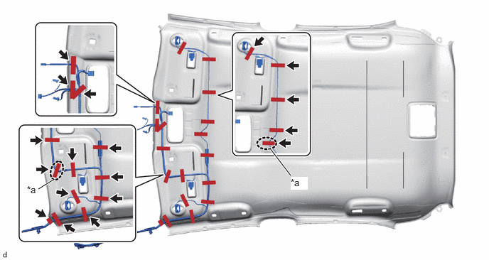
| *a | Adjustment Area | - | - |
for Panoramic Moon Roof:
Line up the No. 1 roof wire positioning tape and the roof headlining markings.
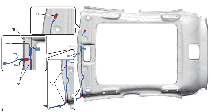
| *a | Positioning Tape | - | - |
Install the No. 1 roof wire with 9 new pieces of adhesive tape.
- NOTICE:
- ·
Apply the tape securely in place.
·Do not touch the adhesive surface when applying the tape to prevent adhesion failure.
- HINT:
-
Adjust the slack of the No. 1 roof wire as shown in the adjustment area of illustration.
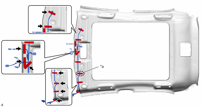
| *a | Adjustment Area | - | - |
82171
4.INSTALL NO. 1 ROOF WIRE (for TMC Made)
|
|
Install in this Direction |
Turn the visor connectors approximately 90° clockwise to connect the visor connector as shown in the illustration.
- HINT:
-
Use the same procedures for the opposite side.
Line up the No. 1 roof wire positioning tape and the roof headlining markings.
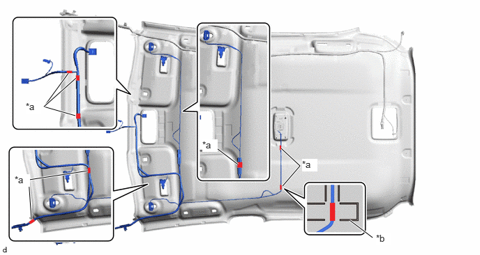
| *a | Positioning Tape | *b | Marking |
Install the No. 1 roof wire with 24 new pieces of adhesive tape.
- NOTICE:
- ·
Apply the tape securely in place.
·Do not touch the adhesive surface when applying the tape to prevent adhesion failure.
- HINT:
-
Adjust the slack of the No. 1 roof wire as shown in the adjustment area of illustration.
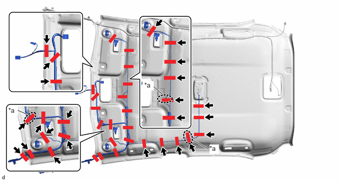
| *a | Adjustment Area | - | - |
63343B
5.INSTALL REAR ROOF SILENCER PAD (for TMC Made)
Align the markings on the roof headlining with the 2 rear roof silencer pads and install them using hot melt glue.
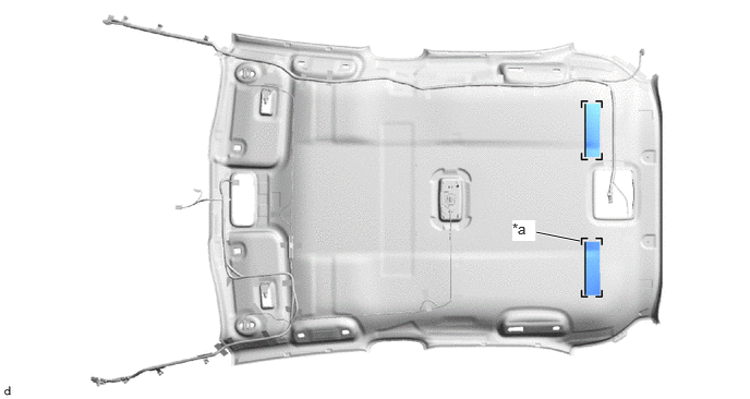
| *a | Marking | - | - |
63341
6.INSTALL NO. 1 ROOF SILENCER PAD (for TMC Made)
Align the markings on the roof headlining with the 3 No. 1 roof silencer pads and install them using hot melt glue.
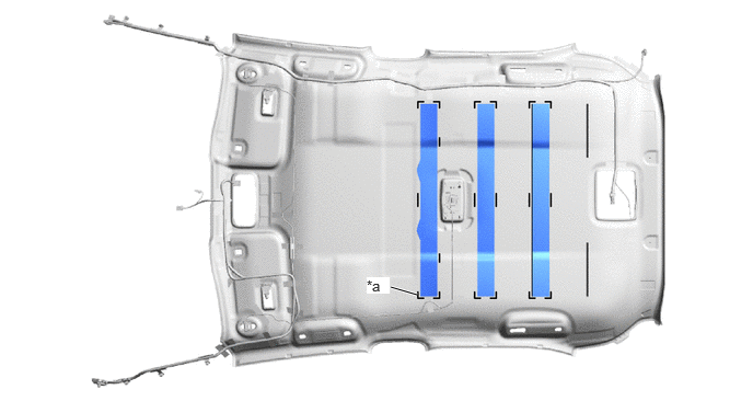
| *a | Marking | - | - |
63342
7.INSTALL NO. 2 ROOF SILENCER PAD (for TMC Made)
Align the markings on the roof headlining with the No. 2 roof silencer pad and install them using hot melt glue.
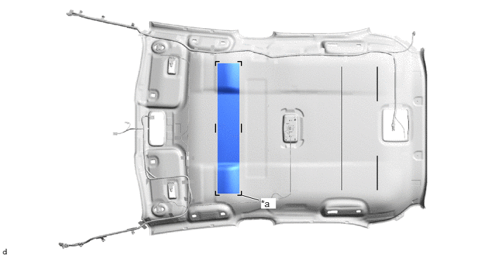
| *a | Marking | - | - |
63345
8.INSTALL NO. 5 ROOF SILENCER PAD (for TMC Made)
Align the markings on the roof headlining with the 2 No. 5 roof silencer pads and install them using hot melt glue.
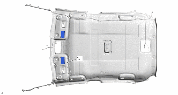
| *a | Marking | - | - |