BRAKE CONTROL / DYNAMIC CONTROL SYSTEMS ELECTRONICALLY CONTROLLED BRAKE SYSTEM(for HV Model TMC Made) Brake Control Warning Light Remains ON
DESCRIPTION
The skid control ECU (brake booster with master cylinder assembly) is connected to the combination meter assembly via CAN communication.
If the skid control ECU (brake booster with master cylinder assembly) stores a DTC, the brake system warning light (yellow indicator) comes on in the combination meter assembly.
WIRING DIAGRAM
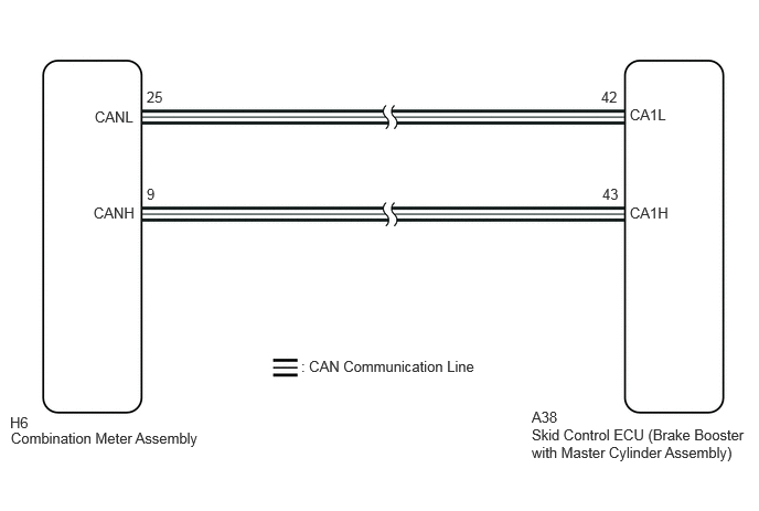
CAUTION / NOTICE / HINT
- NOTICE:
-
After replacing the skid control ECU (brake booster with master cylinder assembly), perform linear solenoid valve offset learning, ABS holding solenoid valve learning, yaw rate and acceleration sensor zero point calibration and system information memorization after performing "Reset Memory".
PROCEDURE
Check if CAN communication system DTCs are output.
- Result:
Result Proceed to DTCs are not output A DTCs are output B
A
B
Check if the skid control ECU (brake booster with master cylinder assembly) connector is securely connected.
- OK:
The connector is securely connected.
- Result:
Proceed to OK NG
OK
NG
Check the auxiliary battery voltage.
- Standard Voltage:
Tester Connection Switch Condition Specified Condition Auxiliary battery Ignition switch ON 11 to 14 V Auxiliary battery Ignition switch ON (READY) 11 to 15.5 V
- Result:
Proceed to OK NG
OK
NG
Perform the Active Test of the combination meter assembly using the GTS.
- Body Electrical > Combination Meter > Active Test
-
Tester Display ECB Warning - 50004 409 110
Check the combination meter assembly.
- OK:
The brake system warning light (yellow indicator) turns on or off in accordance with GTS operation.
- Result:
Proceed to OK NG
OK
NG
Click hereVehicle Interior>METER / GAUGE / DISPLAY>METER / GAUGE SYSTEM>HOW TO PROCEED WITH TROUBLESHOOTING