Home › Drivetrain › EA67F (MANUAL TRANSMISSION / TRANSAXLE) › MANUAL TRANSAXLE SYSTEM › from 2020.09
RM36W0E _52 Drivetrain _095283 EA67F MANUAL TRANSMISSION / TRANSAXLE _0448030 MANUAL TRANSAXLE SYSTEM J

EA67F MANUAL TRANSMISSION / TRANSAXLE  MANUAL TRANSAXLE SYSTEM  Pattern Select Switch iMT Mode Circuit  


DESCRIPTION

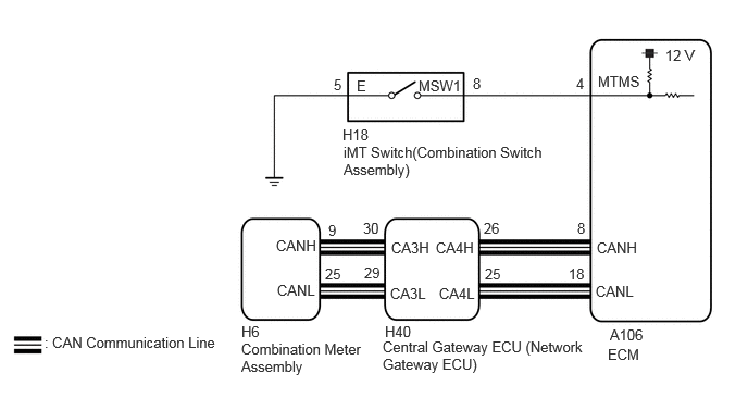
Operating the iMT switch illuminates the iMT indicator light in the combination meter assembly. This displays the iMT system standby condition.

WIRING DIAGRAM
C390260E01
5.729,0.698 6.344,0.896 0.615,0.198 10 false MTMS 6.375,0.448 6.833,0.646 0.458,0.198 10 false 12 V 5.521,0.719 5.833,0.917 0.313,0.198 10 false 4 4.531,0.719 4.844,0.917 0.313,0.198 10 false 8 4.01,0.74 4.417,0.917 0.406,0.177 10 false MSW1 3.417,0.74 3.875,0.938 0.458,0.198 10 false E 3.198,0.729 3.354,0.927 0.156,0.198 10 false 5 5.844,3.125 6.302,3.323 0.458,0.198 10 false A106 5.823,3.313 7.073,3.604 1.25,0.292 10 false ECM 0.427,3.198 2.115,3.677 1.688,0.479 10 false : CAN Communication Line 3.292,1.375 5.25,1.833 1.958,0.458 10 false iMT Switch(Combination Switch Assembly) 3.281,1.208 3.74,1.406 0.458,0.198 10 false H18 2.313,3.26 3.49,3.677 1.177,0.417 10 false Combination Meter Assembly 2.313,3.094 2.625,3.292 0.313,0.198 10 false H6 2.646,2.271 3.26,2.469 0.615,0.198 10 false CANH 2.656,2.698 3.271,2.896 0.615,0.198 10 false CANL 5.719,2.292 6.333,2.49 0.615,0.198 10 false CANH 5.708,2.708 6.323,2.906 0.615,0.198 10 false CANL 5.531,2.104 5.844,2.302 0.313,0.198 10 false 8 5.448,2.542 5.76,2.74 0.313,0.198 10 false 18 3.146,2.125 3.458,2.323 0.313,0.198 10 false 9 3.115,2.542 3.427,2.74 0.313,0.198 10 false 25 3.667,3.24 5.594,3.615 1.927,0.375 10 false Central Gateway ECU (Network Gateway ECU) 4.208,2.729 4.823,2.927 0.615,0.198 10 false CA4L 4.177,2.292 4.792,2.49 0.615,0.198 10 false CA4H 4.635,2.104 4.948,2.302 0.313,0.198 10 false 26 4.646,2.542 4.958,2.74 0.313,0.198 10 false 25 3.74,2.729 4.354,2.927 0.615,0.198 10 false CA3L 3.75,2.292 4.365,2.49 0.615,0.198 10 false CA3H 3.479,2.104 3.792,2.302 0.313,0.198 10 false 30 3.49,2.531 3.802,2.729 0.313,0.198 10 false 29 3.688,3.094 4.146,3.292 0.458,0.198 10 false H40

PROCEDURE

1.CHECK DTC OUTPUT (SFI SYSTEM)
a.

Check for SFI system DTCs.

Click hereEngine / Hybrid System>G16E-GTS (ENGINE CONTROL)>SFI SYSTEM>DTC CHECK / CLEAR

Powertrain > Engine > Trouble Codes
50001 372

Result:
Result Proceed to
DTCs are not output A
DTCs are output B


A

2.INSPECT iMT SWITCH (COMBINATION SWITCH ASSEMBLY)

B

2.INSPECT iMT SWITCH (COMBINATION SWITCH ASSEMBLY)
a.
C381674C56
1.115,1.896 1.406,1.49 true 2.344,1.906 2.042,1.458 true 0.146,0.083 0.458,0.281 0.313,0.198 10 false *a 2.323,1.938 2.792,2.135 0.469,0.198 10 false E 0.75,1.927 1.24,2.125 0.49,0.198 10 false MSW1
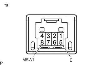
*a Component without harness connected
(iMT Switch (Combination Switch Assembly))


Disconnect the H18 iMT Switch (combination switch assembly) connector.


b.

Measure the resistance according to the value(s) in the table below.

Standard Resistance:
Tester Connection Condition Specified Condition
8 (MSW1) - 5 (E) Switch pushed Below 1 Ω
8 (MSW1) - 5 (E) Switch not pushed 10 kΩ or higher


c.

Connect the H18 iMT Switch (combination switch assembly) connector.


Result:
Proceed to
OK
NG


OK

3.CHECK HARNESS AND CONNECTOR (iMT SWITCH (COMBINATION SWITCH ASSEMBLY) - BODY GROUND)

NG

REPLACE iMT SWITCH (COMBINATION SWITCH ASSEMBLY)

3.CHECK HARNESS AND CONNECTOR (iMT SWITCH (COMBINATION SWITCH ASSEMBLY) - BODY GROUND)
a.

Disconnect the H18 iMT switch (combination switch assembly) connector.


b.

Measure the resistance according to the value(s) in the table below.

Standard Resistance:
Tester Connection Condition Specified Condition
H18-5 (E) - Body ground Always Below 1 Ω


c.

Connect the H18 iMT switch (combination switch assembly) connector.


Result:
Proceed to
OK
NG


OK

4.CHECK HARNESS AND CONNECTOR (iMT SWITCH (COMBINATION SWITCH ASSEMBLY) - ECM)

NG

REPAIR OR REPLACE HARNESS OR CONNECTOR

4.CHECK HARNESS AND CONNECTOR (iMT SWITCH (COMBINATION SWITCH ASSEMBLY) - ECM)
a.

Disconnect the H18 iMT switch (combination switch assembly) connector.


b.

Disconnect the A106 ECM connector.


c.

Measure the resistance according to the value(s) in the table below.

Standard Resistance:
Tester Connection Condition Specified Condition
H18-8 (MSW1) -A106-4 (MTMS) Always Below 1 Ω
H18-8 (MSW1) or A106-4 (MTMS) - Body ground Always 10 kΩ or higher


d.

Connect the A106 ECM connector.


e.

Connect the H18 iMT switch (combination switch assembly) connector.


Result:
Proceed to
OK
NG


OK

NG

REPAIR OR REPLACE HARNESS OR CONNECTOR