METER / GAUGE / DISPLAY METER / GAUGE SYSTEM B150718 Turn Signal Light Circuit Current Below Threshold
DESCRIPTION
This DTC is stored when the combination meter assembly detects an open in a front turn signal light circuit or rear turn signal light circuit.
- HINT:
- ·
If there is an open in a front turn signal light circuit or rear turn signal light circuit, the turn signal lights on the side with the open circuit will blink faster than usual.
·If there is an open in a side turn signal light circuit, DTC B150718 will not be stored.
| DTC No. | Detection Item | DTC Detection Condition | Trouble Area |
|---|---|---|---|
| B150718 | Turn Signal Light Circuit Current Below Threshold | Diagnosis Condition:
Auxiliary battery voltage is 10 V or more Malfunction Status: ·
Open in front turn signal light circuit ·
Open in rear turn signal light circuit |
·
Headlight assembly -
Front turn signal light socket*1 -
Front turn signal light bulb*1 -
Headlight unit assembly LH*2 -
Headlight unit assembly RH*2 -
Wire Harness LH*2 -
Wire Harness RH*2 ·
Rear combination light assembly -
Rear turn signal light socket*3 -
Rear turn signal light bulb*3 -
Rear turn signal light LED*4 ·
Harness or connector ·
Combination meter assembly |
*1: for Halogen Headlight
*2: for LED Headlight
*3: for Rear Turn Signal Light Bulb Type
*4: for Rear Turn Signal Light LED Type
WIRING DIAGRAM
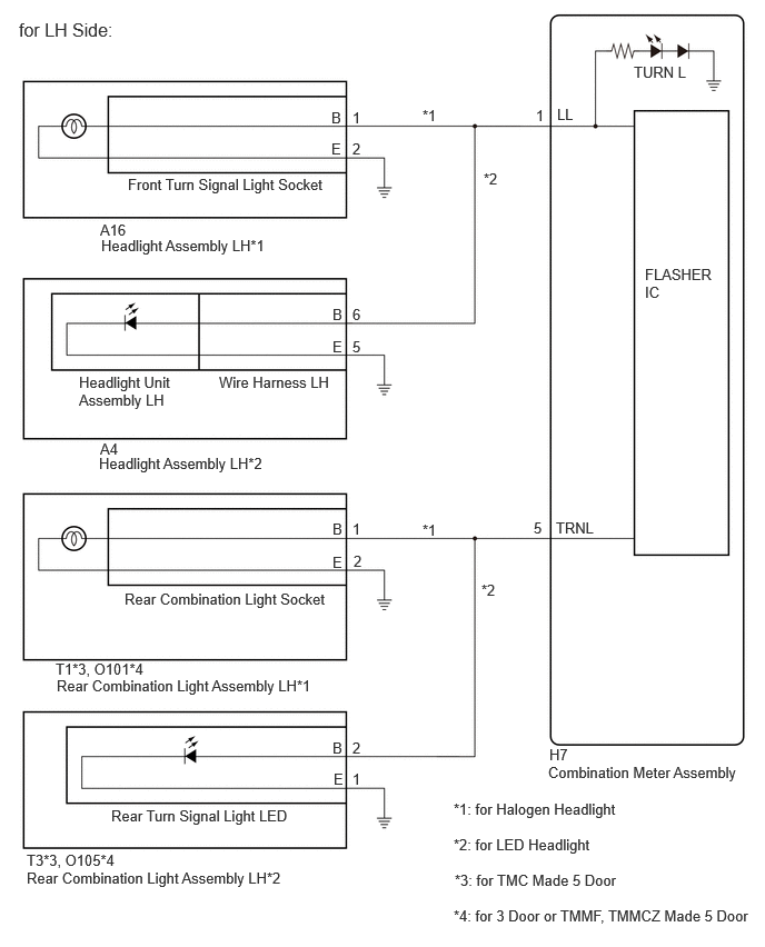
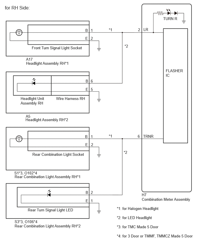
CAUTION / NOTICE / HINT
- NOTICE:
- ·
When replacing the combination meter assembly, always replace it with a new one. If a combination meter assembly which was installed to another vehicle is used, the information stored in it will not match the information from the vehicle and a DTC may be stored.
·Inspect the turn signal light bulbs before performing the following procedure.
PROCEDURE
Check the problem symptoms.
- Result:
Result Proceed to LH side front turn signal light does not blink A LH side rear turn signal light does not blink B RH side front turn signal light does not blink C RH side rear turn signal light does not blink D
A
B
C
D
Check vehicle condition.
- Result:
Result Proceed to for Halogen Headlight A for LED Headlight B
A
B
Pre-procedure1
Interchange the front turn signal light socket LH with RH and connect the connectors.
- HINT:
-
Click hereVehicle Exterior>LIGHTING (EXT)>HEADLIGHT ASSEMBLY (for Halogen Headlight)>DISASSEMBLY
Procedure1
Operate the turn signal switch and check that the LH side front turn signal light operates normally.
- HINT:
-
If the LH side front turn signal light operates normally, the front turn signal light socket is malfunctioning.
Post-procedure1
None
- Result:
Result Proceed to LH side front turn signal light operates normally A LH side front turn signal light does not blink B
A
B
Pre-procedure1
Disconnect the A16 headlight assembly LH connector.
Disconnect the H7 combination meter assembly connector.
Procedure1
Measure the resistance according to the value(s) in the table below.
- Standard Resistance:
Tester Connection Condition Specified Condition A16-1 (B) - H7-1 (LL) Always Below 1 Ω A16-2 (E) - Body ground Always Below 1 Ω
Post-procedure1
None
- Result:
Proceed to OK NG
OK
NG
Pre-procedure1
Interchange the headlight assembly LH with RH and connect the connectors.
Procedure1
Operate the turn signal switch and check that the LH side front turn signal light operates normally.
- HINT:
-
If the RH side front turn signal light operates normally, the headlight assembly LH is malfunctioning.
Post-procedure1
None
- Result:
Result Proceed to LH side front turn signal light operates normally A LH side front turn signal light does not blink B
A
B
Interchange the wire harness LH with RH and connect the connectors.
Operate the turn signal switch and check that the LH side front turn signal light operates normally.
- HINT:
-
If the LH side front turn signal light operates normally, the wire harness is malfunctioning.
- Result:
Result Proceed to LH side front turn signal light operates normally A LH side front turn signal light does not blink B
A
B
Pre-procedure1
Disconnect the A4 headlight assembly LH connector.
Disconnect the H7 combination meter assembly connector.
Procedure1
Measure the resistance according to the value(s) in the table below.
- Standard Resistance:
Tester Connection Condition Specified Condition A4-6 (B) - H7-1 (LL) Always Below 1 Ω A4-5 (E) - Body ground Always Below 1 Ω
Post-procedure1
None
- Result:
Proceed to OK NG
OK
NG
Check vehicle condition.
- Result:
Result Proceed to for Rear Turn Signal Light Bulb Type A for Rear Turn Signal Light LED Type B
A
B
Pre-procedure1
Interchange the rear turn signal light socket LH with RH and connect the connectors.
- HINT:
-
Click hereVehicle Exterior>LIGHTING (EXT)>REAR COMBINATION LIGHT ASSEMBLY (for Halogen Headlight)>DISASSEMBLY
Procedure1
Operate the turn signal switch and check that the LH side rear turn signal light operates normally.
- HINT:
-
If the LH side rear turn signal lights operates normally, the rear turn signal light socket is malfunctioning.
Post-procedure1
None
- Result:
Result Proceed to LH side rear turn signal lights operates normally A LH side rear turn signal light does not blink B
A
Click hereVehicle Exterior>LIGHTING (EXT)>REAR COMBINATION LIGHT ASSEMBLY (for Halogen Headlight)>DISASSEMBLY
B
Check vehicle condition.
- Result:
Result Proceed to for TMC Made 5 Door A for TMMF, TMMCZ Made 5 Door B
A
B
Pre-procedure1
Disconnect the T1 rear combination light assembly LH connector.
Disconnect the H7 combination meter assembly connector.
Procedure1
Measure the resistance according to the value(s) in the table below.
- Standard Resistance:
Tester Connection Condition Specified Condition T1-1 (B) - H7-5 (TRNL) Always Below 1 Ω T1-2 (E) - Body ground Always Below 1 Ω
Post-procedure1
None
- Result:
Proceed to OK NG
OK
NG
Pre-procedure1
Disconnect the O101 rear combination light assembly LH connector.
Disconnect the H7 combination meter assembly connector.
Procedure1
Measure the resistance according to the value(s) in the table below.
- Standard Resistance:
Tester Connection Condition Specified Condition O101-1 (B) - H7-5 (TRNL) Always Below 1 Ω O101-2 (E) - Body ground Always Below 1 Ω
Post-procedure1
None
- Result:
Proceed to OK NG
OK
NG
Pre-procedure1
Interchange the rear turn signal light LED LH with RH and connect the connectors.
- HINT:
-
Click hereVehicle Exterior>LIGHTING (EXT)>REAR COMBINATION LIGHT ASSEMBLY (for LED Headlight)>DISASSEMBLY
Procedure1
Operate the turn signal switch and check that the LH side rear turn signal light operates normally.
- HINT:
-
If the LH side rear turn signal lights operates normally, the rear turn signal light LED is malfunctioning.
Post-procedure1
None
- Result:
Result Proceed to LH side rear turn signal lights operates normally A LH side rear turn signal light does not blink B
A
Click hereVehicle Exterior>LIGHTING (EXT)>REAR COMBINATION LIGHT ASSEMBLY (for LED Headlight)>DISASSEMBLY
B
Check vehicle condition.
- Result:
Result Proceed to for TMC Made 5 Door A for 3 Door or TMMF, TMMCZ Made 5 Door B
A
B
Pre-procedure1
Disconnect the T3 rear combination light assembly LH connector.
Disconnect the H7 combination meter assembly connector.
Procedure1
Measure the resistance according to the value(s) in the table below.
- Standard Resistance:
Tester Connection Condition Specified Condition T3-2 (B) - H7-5 (TRNL) Always Below 1 Ω T3-1 (E) - Body ground Always Below 1 Ω
Pre-procedure1
None
- Result:
Proceed to OK NG
OK
NG
Pre-procedure1
Disconnect the O105 rear combination light assembly LH connector.
Disconnect the H7 combination meter assembly connector.
Procedure1
Measure the resistance according to the value(s) in the table below.
- Standard Resistance:
Tester Connection Condition Specified Condition O105-2 (B) - H7-5 (TRNL) Always Below 1 Ω O105-1 (E) - Body ground Always Below 1 Ω
Pre-procedure1
None
- Result:
Proceed to OK NG
OK
NG
Check vehicle condition.
- Result:
Result Proceed to for Halogen Headlight A for LED Headlight B
A
B
Pre-procedure1
Interchange the front turn signal light socket RH with LH and connect the connectors.
- HINT:
-
Click hereVehicle Exterior>LIGHTING (EXT)>HEADLIGHT ASSEMBLY (for Halogen Headlight)>DISASSEMBLY
Procedure1
Operate the turn signal switch and check that the RH side front turn signal light operates normally.
- HINT:
-
If the RH side front turn signal light operates normally, the front turn signal light socket is malfunctioning.
Post-procedure1
None
- Result:
Result Proceed to RH side front turn signal light operates normally A RH side front turn signal light does not blink B
A
B
Pre-procedure1
Disconnect the A17 headlight assembly RH connector.
Disconnect the H7 combination meter assembly connector.
Procedure1
Measure the resistance according to the value(s) in the table below.
- Standard Resistance:
Tester Connection Condition Specified Condition A17-1 (B) - H7-2 (LR) Always Below 1 Ω A17-2 (E) - Body ground Always Below 1 Ω
Post-procedure1
None
- Result:
Proceed to OK NG
OK
NG
Pre-procedure1
Interchange the headlight assembly RH with LH and connect the connectors.
Procedure1
Operate the turn signal switch and check that the RH side front turn signal light operates normally.
- HINT:
-
If the RH side front turn signal light operates normally, the headlight assembly RH is malfunctioning.
Post-procedure1
None
- Result:
Result Proceed to RH side front turn signal light operates normally A RH side front turn signal light does not blink B
A
B
Pre-procedure1
Interchange the wire harness RH with LH and connect the connectors.
Procedure1
Operate the turn signal switch and check that the RH side front turn signal light operates normally.
- HINT:
-
If the RH side front turn signal light operates normally, the wire harness RH is malfunctioning.
Post-procedure1
None
- Result:
Result Proceed to RH side front turn signal light operates normally A RH side front turn signal light does not blink B
A
B
Pre-procedure1
Disconnect the A5 headlight assembly RH connector.
Disconnect the H7 combination meter assembly connector.
Procedure1
Measure the resistance according to the value(s) in the table below.
- Standard Resistance:
Tester Connection Condition Specified Condition A5-6 (B) - H7-2 (LR) Always Below 1 Ω A5-5 (E) - Body ground Always Below 1 Ω
Post-procedure1
None
- Result:
Proceed to OK NG
OK
NG
Check vehicle condition.
- Result:
Result Proceed to for Rear Turn Signal Light Bulb Type A for Rear Turn Signal Light LED Type B
A
B
Pre-procedure1
Interchange the rear turn signal light socket RH with LH and connect the connectors.
- HINT:
-
Click hereVehicle Exterior>LIGHTING (EXT)>REAR COMBINATION LIGHT ASSEMBLY (for Halogen Headlight)>DISASSEMBLY
Procedure1
Operate the turn signal switch and check that the RH side rear turn signal light operates normally.
- HINT:
-
If the RH side rear turn signal lights operates normally, the rear turn signal light socket is malfunctioning.
Post-procedure1
None
- Result:
Result Proceed to RH side rear turn signal lights operates normally A RH side rear turn signal light does not blink B
A
Click hereVehicle Exterior>LIGHTING (EXT)>REAR COMBINATION LIGHT ASSEMBLY (for Halogen Headlight)>DISASSEMBLY
B
Check vehicle condition.
- Result:
Result Proceed to for TMC Made 5 Door A for TMMF, TMMCZ Made 5 Door B
A
B
Pre-procedure1
Disconnect the S1 rear combination light assembly RH connector.
Disconnect the H7 combination meter assembly connector.
Procedure1
Measure the resistance according to the value(s) in the table below.
- Standard Resistance:
Tester Connection Condition Specified Condition S1-1 (B) - H7-6 (TRNR) Always Below 1 Ω S1-2 (E) - Body ground Always Below 1 Ω
Post-procedure1
None
- Result:
Proceed to OK NG
OK
NG
Pre-procedure1
Disconnect the O102 rear combination light assembly RH connector.
Disconnect the H7 combination meter assembly connector.
Procedure1
Measure the resistance according to the value(s) in the table below.
- Standard Resistance:
Tester Connection Condition Specified Condition O102-1 (B) - H7-6 (TRNR) Always Below 1 Ω O102-2 (E) - Body ground Always Below 1 Ω
Post-procedure1
None
- Result:
Proceed to OK NG
OK
NG
Pre-procedure1
Interchange the rear turn signal light LED RH with LH and connect the connectors.
- HINT:
-
Click hereVehicle Exterior>LIGHTING (EXT)>REAR COMBINATION LIGHT ASSEMBLY (for LED Headlight)>DISASSEMBLY
Procedure1
Operate the turn signal switch and check that the RH side rear turn signal light operates normally.
- HINT:
-
If the RH side rear turn signal lights operates normally, the rear turn signal light LED is malfunctioning.
Post-procedure1
None
- Result:
Result Proceed to RH side rear turn signal lights operates normally A RH side rear turn signal light does not blink B
A
Click hereVehicle Exterior>LIGHTING (EXT)>REAR COMBINATION LIGHT ASSEMBLY (for LED Headlight)>DISASSEMBLY
B
Check vehicle condition.
- Result:
Result Proceed to for TMC Made 5 Door A for 3 Door or TMMF, TMMCZ Made 5 Door B
A
B
Pre-procedure1
Disconnect the S3 rear combination light assembly RH connector.
Disconnect the H7 combination meter assembly connector.
Procedure1
Measure the resistance according to the value(s) in the table below.
- Standard Resistance:
Tester Connection Condition Specified Condition S3-2 (B) - H7-6 (TRNR) Always Below 1 Ω S3-1 (E) - Body ground Always Below 1 Ω
Post-procedure1
None
- Result:
Proceed to OK NG
OK
NG
Pre-procedure1
Disconnect the O106 rear combination light assembly RH connector.
Disconnect the H7 combination meter assembly connector.
Procedure1
Measure the resistance according to the value(s) in the table below.
- Standard Resistance:
Tester Connection Condition Specified Condition O106-2 (B) - H7-6 (TRNR) Always Below 1 Ω O106-1 (E) - Body ground Always Below 1 Ω
Post-procedure1
None
- Result:
Proceed to OK NG
OK
NG