FREEZE FRAME DATA
Troubleshooting · Vehicles built from Aug 2005
| FREEZE FRAME DATA |
- HINT:
- Whenever a DTC is detected or the ABS operates, the skid control ECU stores the current vehicle (sensor) state as freeze frame data.
- The skid control ECU stores the number of times (maximum: 31) the ignition switch has been turned from off to on (IG) since the last time the ABS was activated. However, if the vehicle was stationary or running at a low speed (7 km/h [4.3 mph] or less), or if a DTC is detected, the skid control ECU stops counting.
- Freeze frame data at the time the ABS operates:
The skid control ECU stores and updates the data whenever the ABS system operates.
When the ECU stores data at the time a DTC is detected, the data stored when the ABS operated is erased.
- Freeze frame data at the time a DTC is detected:
When the skid control ECU stores data at the time a DTC is detected, no updates will be performed until the data is cleared.
- Whenever a DTC is detected or the ABS operates, the skid control ECU stores the current vehicle (sensor) state as freeze frame data.
Connect the intelligent tester to the DLC3.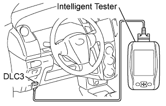

Turn the ignition switch on (IG).
Turn the tester on.
From the display on the tester, select "FREEZE FRAME DATA".
Item (Display)
Measurement Item
Reference Values
Elapsed Time after Freeze Trigger
Elapsed time after freeze frame data recorded
Min.: 0 ms
Max.: 500 ms
Number of IG ON
Number of ignition switch on operations since freeze frame data stored
1 to 31
Buzzer
Skid control buzzer signal
ON: Skid control buzzer ON
OFF: Skid control buzzer OFF
Stop Lamp SW
Stop light switch signal
ON: Stop light switch ON
OFF: Stop light switch OFF
Parking Brake SW
Parking brake switch signal
ON: Parking brake switch ON
OFF: Parking brake switch OFF
Gear Position
Gear position information
FAIL
1st
2nd
3rd
4th
5th
6th
P, N
R
NOT R
Shift Lever Position
Shift lever position information
FAIL
1st
2nd
3rd
4th
5th
6th/B
D/M
P, N
R
Operated System
Operated system status
ABS: ABS activated
VSC: VSC activated
TRC: TRC activated
BA: BA activated
FAIL: Fail safe mode activated
SYS: System prohibited
NON: No system activated
Master Cylinder Sensor
Master cylinder pressure sensor reading
Brake pedal released: 0.3 V to 0.9 V
Brake pedal depressed: 0.8 V to 4.5 V
M/C Sensor Grade
Master cylinder pressure sensor change
Min.: -30 MPa/s
Max.: 200 MPa/s
Yaw Rate Sensor
Yaw rate sensor reading
Min.: -128 deg/s
Max.: 127 deg/s
Steering Angle Sensor
Steering sensor reading
Left turn: Increase
Right turn: Decrease
Lateral G
Lateral G
Min.: -25.11 m/s2
Max.: 24.91 m/s2
Forward and Rearward G
Forward and backward G
Min.: -25.11 m/s2
Max.: 24.91 m/s2
FR Wheel Speed
FR wheel speed
Min.: 0 km/h (0 mph)
Max.: 326 km/h (202 mph)
FL Wheel Speed
FL wheel speed
Min.: 0 km/h (0 mph)
Max.: 326 km/h (202 mph)
RR Wheel Speed
RR wheel speed
Min.: 0 km/h (0 mph)
Max.: 326 km/h (202 mph)
RL Wheel Speed
RL wheel speed
Min.: 0 km/h (0 mph)
Max.: 326 km/h (202 mph)
Vehicle Speed
Vehicle speed
Min.: 0 km/h (0 mph)
Max.: 326 km/h (202 mph)
Vehicle Speed Grade
Vehicle speed grade
Min.: -25.11 m/s2
Max.: 24.91 m/s2
Real Engine Torque
Real engine torque
Min.: -1024 Nm
Max.: 1023 Nm
Accelerator Opening Angle %
Accelerator pedal opening angle %
Min.: 0 %
Max.: 128 %