TEST MODE PROCEDURE
Troubleshooting · Vehicles built from Nov 2005
- HINT:
- By switching the skid control ECU from normal mode to test mode, abnormality detection sensitivity is enhanced and troubleshooting can be conducted efficiently.
- Perform a sensor check in test mode after the speed sensor or sensor rotor has been repaired or replaced.
- If the ignition switch is turned from on to ACC or off during test mode, DTCs related to the signal check function will be erased.
- During test mode, the skid control ECU stores all DTCs related to the signal check function, and the DTCs are erased if normality is confirmed. Any remaining DTCs are those indicating abnormalities that were found.
- By switching the skid control ECU from normal mode to test mode, abnormality detection sensitivity is enhanced and troubleshooting can be conducted efficiently.
| TEST MODE (SIGNAL CHECK) PROCEDURE (for Using a Intelligent Tester) |
Turn the ignition switch off.
Check that the steering wheel is in the straight-ahead position.
Check that the shift lever is in neutral and apply the parking brake.
- HINT:
- Application of the parking brake is not included in the conditions for the commencement of test mode.
Connect the intelligent tester to the DLC3.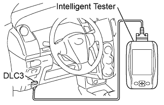

Turn the ignition switch on (IG).
Turn the tester on.
Switch the skid control ECU to test mode using the intelligent tester.
Select the following menu items: Chassis / ABS/VSC/TRC / Utility / Signal Check.
Check that the ABS warning light and VSC warning light blink as shown in the illustration.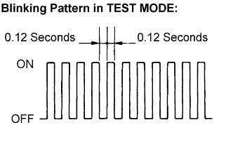
Start the engine.
| TEST MODE (SIGNAL CHECK) PROCEDURE (for Using a SST Check Wire) |
Turn the ignition switch off.
Check that the steering wheel is in the straight-ahead position.
Check that the shift lever is in neutral and apply the parking brake.
- HINT:
- Application of the parking brake is not included in the conditions for the commencement of test mode.
Using SST, connect terminals TS and CG of the DLC3.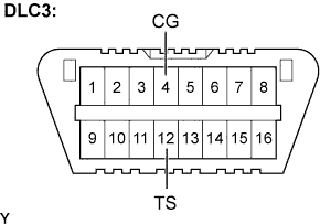
- SST
- 09843-18040
Turn the ignition switch on (IG).
Check that the ABS warning light and VSC warning light blink as shown in the illustration.
Start the engine.
| MASTER CYLINDER PRESSURE SENSOR CHECK |
Leave the vehicle in a stationary condition and release the brake pedal for 1 second or more, and quickly depress the brake pedal with a force of 98 N (10 kgf, 22 lbf) or more for 1 second.
Check that the skid control buzzer beeps for 1 second.
- HINT:
- Ensure that the skid control buzzer beeps.
| YAW RATE SENSOR CHECK |
Release the parking brake and drive the vehicle at a speed of 3 km/h (2 mph) or more, and turn the steering wheel either to the left or right 90° or more to turn the vehicle through 180 degrees.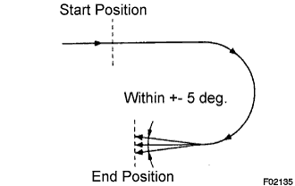
Stop the vehicle, move the shift lever into neutral, and then apply the parking brake.
Check that the skid control buzzer sounds for 3 seconds.
- HINT:
- If the signal check has been completed normally, the skid control buzzer sounds and DTC C0371/71 will be deleted.
- If the skid control buzzer does not sound, check the skid control buzzer circuit (Click here).
- If the skid control buzzer still does not sound, there is a malfunction in the yaw rate sensor, so check for DTCs.
- Drive the vehicle in a 180° semi circle. At the end of the turn, the direction of the vehicle should be within 180° +-5° of its start position.
- Do not spin the wheels.
- If the signal check has been completed normally, the skid control buzzer sounds and DTC C0371/71 will be deleted.
| DECELERATION SENSOR CHECK |
Release the parking brake and drive the vehicle at a speed of 3 km/h (2 mph) or more, and turn the steering wheel either to the left or right 90° or more to turn the vehicle through 180 degrees.
Check that the skid control buzzer sounds for 3 seconds while the vehicle is turning.
- HINT:
- The skid control ECU checks whether the lateral acceleration reaches 0.1 G or more while the vehicle is turning. When the lateral acceleration reaches 0.1 G, the skid control buzzer sounds for 3 seconds. Be sure to check that the buzzer sound.
- The table shows the vehicle speeds and turning radius under which the lateral acceleration reaches 0.1 G or more.
Reference Vehicle Speed
km/h (mph)
Turning Radius
m (ft)
10 (6)
7.87 (25.82)
15 (9)
17.72 (58.13)
20 (12)
31.49 (103.31)
25 (16)
49.21 (161.45)
- If the signal check has been completed normally, the skid control buzzer sounds and DTC C1279/79 will be deleted.
- If the skid control buzzer does not sound, check the skid control buzzer circuit (Click here).
- If the skid control buzzer still does not sound, there is a malfunction in the deceleration sensor, so check for DTCs.
- Do not spin the wheels.
- The skid control ECU checks whether the lateral acceleration reaches 0.1 G or more while the vehicle is turning. When the lateral acceleration reaches 0.1 G, the skid control buzzer sounds for 3 seconds. Be sure to check that the buzzer sound.
| SPEED SENSOR CHECK |
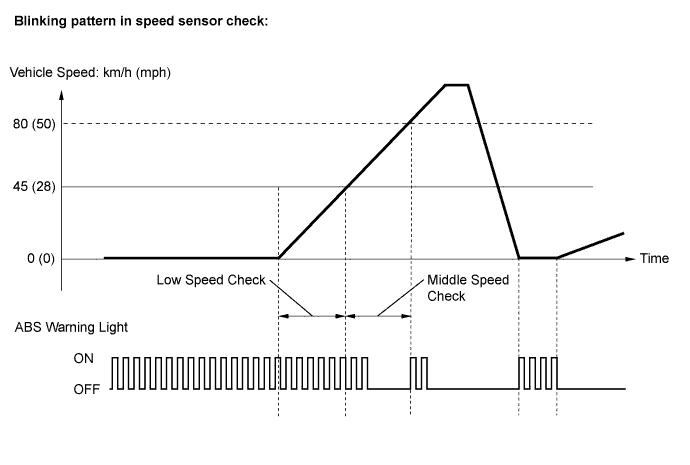
Check that the ABS warning light is blinking as shown in the illustration.
Check the speed sensor signal.
Drive the vehicle straight forward at a speed of 45 km/h (28 mph) or more for several seconds.
Check that the ABS warning light goes off.
- HINT:
- The speed sensor check may not be completed if the sensor check is started with the steering wheel turned or one or more wheels spinning.
- If the speed sensor check is commenced while the steering wheel is turned, the ABS warning light may come on after the low speed check is finished.
- The ABS warning light comes on immediately when an abnormality is detected.
- When the speed sensor signal is normal, the ABS warning light goes off while driving at 45 km/h (28 mph) or more and blinks in the test mode pattern while stationary.
- Do not drive the vehicle at a speed of 80 km/h (50 mph) or more after the ABS warning light turns off, because test mode DTCs are set again when the vehicle speed exceeds 80 km/h (50 mph).
- If the vehicle is driven on extremely rough or bumpy roads, sensor signal check may fail and middle speed check DTCs may not be deleted. In such cases, stop the vehicle and drive it again to resume the speed sensor check.
- The speed sensor check may not be completed if the sensor check is started with the steering wheel turned or one or more wheels spinning.
Stop the vehicle.
| END OF SENSOR CHECK |
When the sensor check is successfully completed, the ABS warning light blinks in the test mode pattern when the vehicle is stopped, and goes off when the vehicle is driven.
- NOTICE:
- If the sensor check is not completed, the ABS warning light blinks even while the vehicle is driving and the ABS does not operate.
| READ SIGNAL CHECK FUNCTION DTCs (for Using a Intelligent Tester) |
Read the DTC(s) by following the instructions on the tester screen.
| READ SENSOR SIGNAL CHECK FUNCTION DTCs (for Using a SST Check Wire) |
Using SST, connect terminals TC and CG of the DLC3.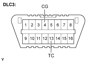
- SST
- 09843-18040
Turn the ignition switch on (IG).
Read the number of blinks of the ABS warning light.
- HINT:
-
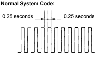
- If all sensors are normal, a normal system code is output (the light comes on for 0.25 seconds at intervals of 0.25 seconds).
After the check, disconnect the SST from terminals TC and CG of the DLC3.
Turn the ignition switch off.
| SENSOR SIGNAL CHECK FUNCTION DTCs |
| DTC No. |
Diagnosis |
Trouble Areas |
| C1271/71 |
Low output signal of front speed sensor RH |
|
| C1272/72 |
Low output signal of front speed sensor LH |
|
| C1273/73 |
Low output signal of rear speed sensor RH |
|
| C1274/74 |
Low output signal of rear speed sensor LH |
|
| C1275/75 |
Abnormal change in output signal of front speed sensor RH |
|
| C1276/76 |
Abnormal change in output signal of front speed sensor LH |
|
| C1277/77 |
Abnormal change in output signal of rear speed sensor RH |
|
| C1278/78 |
Abnormal change in output signal of rear speed sensor LH |
|
| C1279/79 |
Deceleration sensor output voltage malfunction |
|
| C1281/81 |
Master cylinder pressure sensor output malfunction |
Master cylinder pressure sensor |
| DTC No. |
Diagnosis |
Trouble Areas |
| C0371/71 |
Yaw rate sensor |
Yaw rate sensor |
- HINT:
- The DTCs in this table are only output in test mode.
- Detection of DTCs from C1271/71 to C1274/74 is completed before the vehicle speed reaches 5 km/h (3 mph).
- Detection of DTCs from C1275/75 to C1278/78 is completed before the vehicle speed reaches 45 km/h (28 mph).
- C1271/71 - C1274/74: Speed sensor output from only one wheel is extremely low despite the other wheel speed outputs reaching 5 km/h (3 mph).
-
C1275/75 - C1278/78: Abnormal speed sensor output frequency is as shown in the illustration.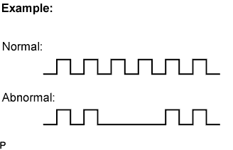
- The DTCs in this table are only output in test mode.