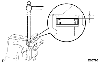
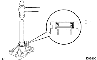
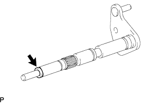
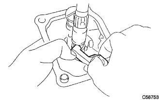
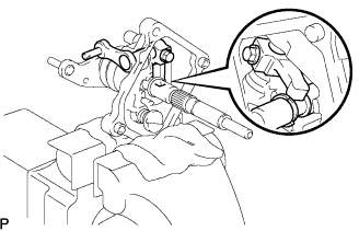
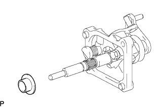
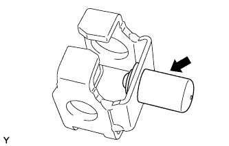
Install a new spacer onto the shift and select lever shaft.
Install the shift lever boot onto the shift and select lever shaft.
Install the shift and select lever shaft with the shift lever boot onto the control shaft cover.
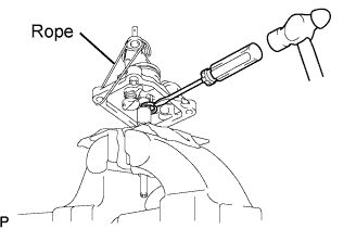
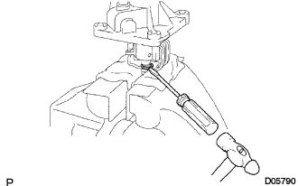
Using a screwdriver and hammer, tap a new snap ring onto the shift and select lever shaft.
HINT:
Lifting the control shaft cover up with a piece of rope or the equivalent makes the work easier.
4.
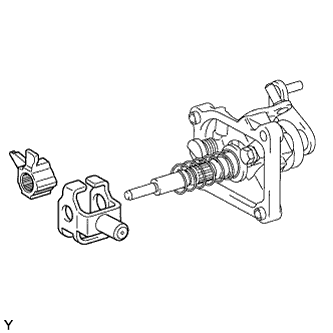
INSTALL SELECT INNER LEVER
Install the select inner lever onto the control shaft cover.
5.
INSTALL SELECT LEVER SHAFT
Apply sealant to the bolt threads.
Sealant:
Part No. 08833-00080, THREE BOND 1344, LOCTITE 242 or the equivalent
Install the select lever shaft onto the select inner lever and the control shaft cover with the bolt.
Torque:
38 N*m{
387 kgf*cm
, 28 ft.*lbf
}
NOTICE:
Fit the edge of the select inner lever into the groove of the select lever shaft, as shown in the illustration.
6.
INSTALL SELECT SPRING SEAT NO.2
Install the select spring seat No. 2 onto the shift and select lever shaft.
7.
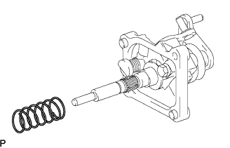
INSTALL SELECT RETURN COMPRESSION SPRING
Install the select return compression spring onto the shift and select lever shaft.
8.
INSTALL LOCK BALL HOLDER
Install the lock ball holder.
9.
INSTALL SHIFT LEVER INNER NO.1
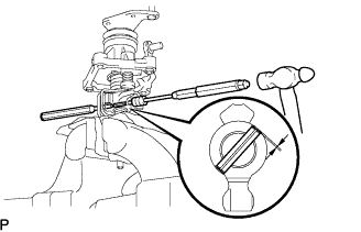
Install shift lever inner No. 1 and the shift interlock plate onto the shift and select lever shaft.
While pushing up the No. 1 shift inner lever so that the hole in the inner lever aligns with the hole in the shift and select lever shaft, insert a pin punch half way into the inner lever, and using another pin punch and a hammer, drive in the slotted spring pin. When the No. 1 shift inner lever is fixed with the slotted spring pin, pull out the pin punch while holding the inner lever.
Drive in depth:
-0.5 to 0.5 mm (-0.020 to 0.020 in.)
Using a screwdriver and hammer, tap a new snap ring onto the shift and select lever shaft.