Power Source Circuit
Circuit diagnosis · Vehicles built from Aug 2005
DESCRIPTION
This circuit supplies power source voltage from the battery to terminal B of the steering lock actuator assembly.The diagnosis information of the steering lock ECU is transmitted to the tester via the certification ECU as the steering lock ECU is not connected to the CAN communication system.
WIRING DIAGRAM
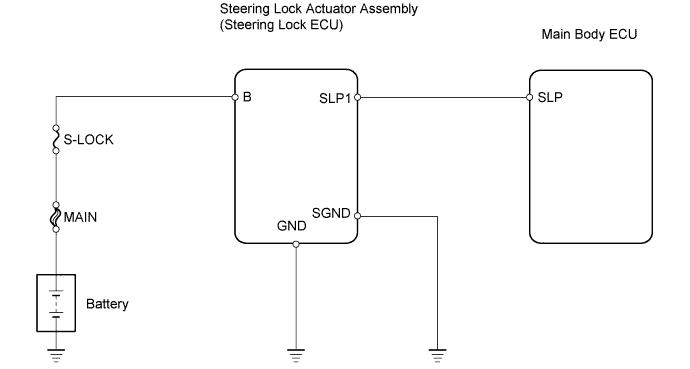

INSPECTION PROCEDURE
- HINT:
- Before starting the inspection by using the intelligent tester with the engine switch off, make sure that the driver door is open.
- When the engine switch is off, the main body ECU may not be working.
- Communication with the intelligent tester is impossible if the main body ECU is not working.
- Before starting the inspection by using the intelligent tester with the engine switch off, make sure that the driver door is open.
| 1. CHECK HARNESS AND CONNECTOR (STEERING LOCK ACTUATOR ASSEMBLY - BODY GROUND) |

Disconnect the connector from the steering lock actuator assembly.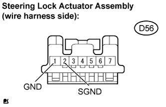
Measure the resistance.
- Standard resistance:
Tester Connection
Condition
Specified Condition
GND (D56-1) - Body ground
Always
Below 1 Ω
SGND (D56-2) - Body ground
Always
Below 1 Ω
|
|
||||

| OK | |
 |
| 2. CHECK HARNESS AND CONNECTOR (STEERING LOCK ACTUATOR ASSEMBLY - BATTERY) |
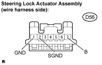 |
Measure the voltage.
- Standard voltage:
Tester Connection
Condition
Specified Condition
B (D56-7) - GND (D56-1)
Always
10 to 14 V
B (D56-7) - SGND (D56-2)
Always
10 to 14 V
|
|
||||
| OK | ||
 |
||
| ||