P0031 Oxygen Sensor Heater Control Circuit Low (Bank 1 Sensor 1)
Diagnostic trouble codes · Vehicles built from Nov 2005
Also covers:
- P0032 Oxygen Sensor Heater Control Circuit High (Bank 1 Sensor 1)
- P0037 Oxygen Sensor Heater Control Circuit Low (Bank 1 Sensor 2)
- P0038 Oxygen Sensor Heater Control Circuit High (Bank 1 Sensor 2)
CAUTION / NOTICE / HINT
- HINT:
- Sensor 1 refers to the sensor mounted in front of the Three-Way Catalytic Converter (TWC) and located near the engine assembly.
- Sensor 2 refers to the sensor mounted behind the TWC and located far from the engine assembly.
- Sensor 1 refers to the sensor mounted in front of the Three-Way Catalytic Converter (TWC) and located near the engine assembly.
DESCRIPTION
- Refer to DTC P0130 for sensor 1 (Click here).
- Refer to DTC P0136 for sensor 2 (Click here).
- HINT:
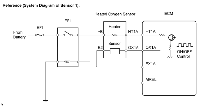
- The ECM has an ON/OFF control circuit to flow the current through the heater. The heated oxygen sensor heater circuit uses a relay on the +B side of the circuit.

| DTC No. |
DTC Detection Conditions |
Trouble Areas |
| P0031 P0037 |
Heated Oxygen (HO2) sensor heater current below 0.25 A when heater operates with +B greater than 10.5 V (1 trip detection logic) |
|
| P0032 P0038 |
HO2 sensor heater current exceeds 2 A when heater operates (1 trip detection logic) |
|
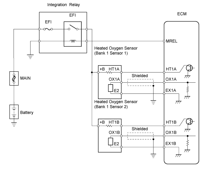
WIRING DIAGRAM
INSPECTION PROCEDURE
- HINT:
- Read freeze frame data using an intelligent tester. Freeze frame data records the engine conditions when a malfunction is detected. When troubleshooting, freeze frame data can help determine if the vehicle was running or stopped, if the engine was warmed up or not, if the air-fuel ratio was LEAN or RICH, and other data from the time the malfunction occurred.
- Sensor 1 refers to the sensor closest to the engine body.
- Sensor 2 refers to the sensor farthest away from the engine body.
- Read freeze frame data using an intelligent tester. Freeze frame data records the engine conditions when a malfunction is detected. When troubleshooting, freeze frame data can help determine if the vehicle was running or stopped, if the engine was warmed up or not, if the air-fuel ratio was LEAN or RICH, and other data from the time the malfunction occurred.
| 1. INSPECT HEATED OXYGEN SENSOR (HEATER RESISTANCE) |

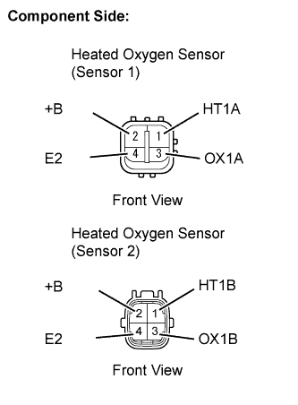 |
Disconnect the C42 or C43 Heated Oxygen (HO2) sensor connector.
Measure the resistance between the terminals of the HO2 sensor connector.
- Standard resistance (Sensor 1):
Tester Connections
Specified Conditions
HT1A (1) - +B (2)
5 to 10 Ω at 20°C (68°F)
HT1A (1) - E2 (4)
10 kΩ or higher
- Standard resistance (Sensor 2):
Tester Connections
Specified Conditions
HT1B (1) - +B (2)
11 to 16 Ω at 20°C (68°F)
HT1B (1) - E2 (4)
10 kΩ or higher
Reconnect the HO2 sensor connector.
|
|
||||

| OK | |
 |
| 2. CHECK TERMINAL VOLTAGE (+B OF HO2 SENSOR) |
Disconnect the C42 or C43 HO2 sensor connector.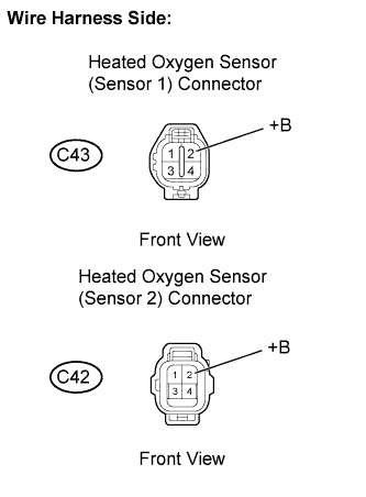
Turn the ignition switch on (IG).
Measure the voltage between the terminals of the C42 or C43 HO2 sensor connector and body ground.
- Standard voltage:
Tester Connections
Specified Conditions
+B (C42-2) - Body ground
9 to 14 V
+B (C43-2) - Body ground
Reconnect the HO2 sensor connector.
|
|
||||

| NG | |
|
| 3. INSPECT INTEGRATION RELAY (EFI FUSE AND EFI RELAY) |
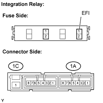 |
Remove the integration relay from the engine room relay block.
Inspect the EFI fuse.
Remove the EFI fuse from the integration relay.
Check the EFI fuse resistance.
- Standard resistance:
- Below 1 Ω
Reinstall the EFI fuse.
Inspect the EFI relay.
Check the EFI relay resistance.
- Standard resistance:
Tester Connections
Specified Conditions
1C-1 - 1A-4
10 kΩ or higher
Below 1 Ω
(Apply battery voltage between terminals 1A-2 and 1A-3)
Reinstall the integration relay.
|
|
||||
| OK | |
|
| 4. CHECK HARNESS AND CONNECTOR (HO2 SENSOR - EFI RELAY) |
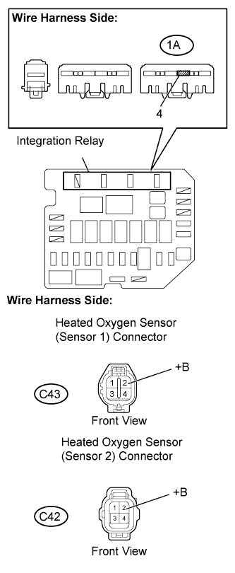 |
Disconnect the C42 or C43 HO2 sensor connector.
Remove the integration relay from the engine room relay block.
Check the resistance.
- Standard resistance (Check for open):
Tester Connections
Specified Conditions
+B (C42-2) - Engine room relay block (1A-4)
Below 1 Ω
+B (C43-2) - Engine room relay block (1A-4)
- Standard resistance (Check for short):
Tester Connections
Specified Conditions
+B (C42-2) or Engine room relay block (1A-4) - Body ground
10 kΩ or higher
+B (C43-2) or Engine room relay block (1A-4) - Body ground
Reconnect the HO2 sensor connector.
Reinstall the integration relay.
|
|
||||
| OK | ||
 |
||
| ||
| 5. CHECK HARNESS AND CONNECTOR (HO2 SENSOR - ECM) |
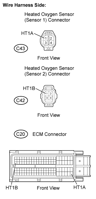 |
Disconnect the C42 or C43 HO2 sensor connector.
Disconnect the C20 ECM connector.
Check the resistance.
- Standard resistance (Check for open):
Tester Connections
Specified Conditions
HT1B (C42-1) - HT1B (C20-47)
Below 1 Ω
HT1A (C43-1) - HT1A (C20-109)
- Standard resistance (Check for short):
Tester Connections
Specified Conditions
HT1B (C42-1) or HT1B (C20-47) - Body ground
10 kΩ or higher
HT1A (C43-1) or HT1A (C20-109) - Body ground
Reconnect the HO2 sensor connector.
Reconnect the ECM connector.
|
|
||||
| OK | |
|
| 6. CHECK WHETHER DTC OUTPUT RECURS (DTC P0031, P0032, P0037 OR P0038) |
Connect an intelligent tester to the DLC3.
Turn the ignition switch on (IG) and turn the tester on.
Clear DTCs (Click here).
Start the engine.
Allow the engine to idle for 1 minute or more.
Select the following menu items: Powertrain / Engine and ECT / DTC.
Read DTCs.
- Result:
Display (DTC Output)
Proceed To
No output
A
P0031, P0032, P0037 or P0038
B
|
|
||||
| A | ||
|
||
| ||