ECU Power Source Circuit
Circuit diagnosis · Vehicles built from Nov 2006
DESCRIPTION
This circuit provides power to operate the theft warning ECU.WIRING DIAGRAM
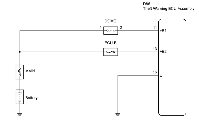

INSPECTION PROCEDURE
| 1. INSPECT FUSE (ECU-B, DOME) |

Remove the ECU-B fuse and DOME fuse from the engine room R/B.
Measure the resistance.
- Standard resistance:
- Below 1 Ω
Reinstall the fuses.
|
|
||||

| OK | |
 |
| 2. INSPECT THEFT WARNING ECU ASSEMBLY |
Remove the theft warning ECU assembly without disconnecting the D86 connector.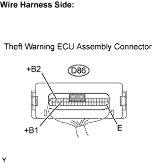
Measure the voltage.
- Standard voltage:
Tester Connection
Condition
Specified Condition
D86-11 (+B1) - D86-16 (E)
Always
11 to 14 V
D86-13 (+B2) - D86-16 (E)
Always
11 to 14 V
|
|
||||

| OK | ||
 |
||
| ||
| 3. CHECK HARNESS AND CONNECTOR (POWER SOURCE) |
Disconnect the D86 theft warning ECU connector.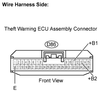
Measure the voltage.
- Standard voltage:
Tester Connection
Condition
Specified Condition
D86-11 (+B1) - Body ground
Always
11 to 14 V
D86-13 (+B2) - Body ground
Always
11 to 14 V
Check the resistance.
- Standard resistance:
Tester Connection
Specified Condition
D86-16 (E) - Body ground
Below 1 Ω
Reconnect the theft warning ECU connector.
|
|
||||
| OK | ||
|
||
| ||