P0500 Vehicle Speed Sensor "A"
Diagnostic trouble codes · Vehicles built from Nov 2005
DESCRIPTION
Vehicles, which are equipped with the ABS (Anti-Lock Brake System), detect the vehicle speed using the skid control ECU and wheel speed sensor. The wheel speed sensor monitors the wheel rotation speed and sends a signal to the skid control ECU. The skid control ECU converts the wheel speed signal into a 4-pulse signal and transmits it to the transmission control ECU via the combination meter. The transmission control ECU determines the vehicle speed based on the frequency of the pulse signal.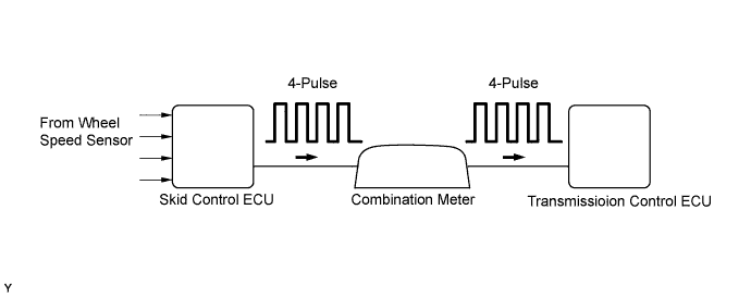

| DTC No. |
DTC Detection Conditions |
Trouble Areas |
| P0500 |
The transmission control ECU detects the following conditions simultaneously for 4 seconds or more: (1 trip detection logic)
|
|
WIRING DIAGRAM
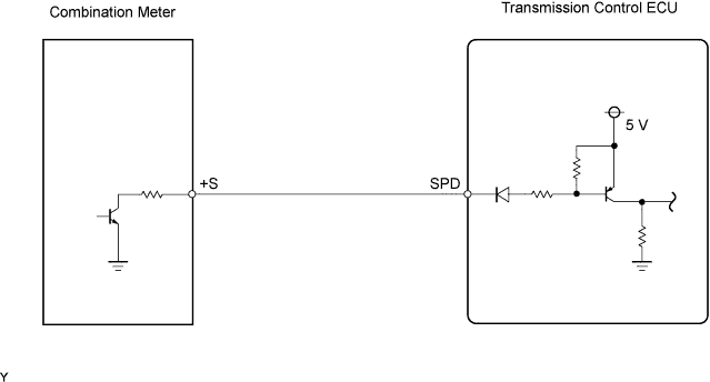
When a DTC P0500 is output, a ground short in the wiring of terminal SPD or an internal ground short in the relevant ECU is suspected.
INSPECTION PROCEDURE
| 1. CHECK OPERATION OF SPEEDOMETER |

Drive the vehicle and check if the function of the speedometer in the combination meter is normal.
- OK:
- Actual vehicle speed and the speed indicated on the speedometer are the same.
- HINT:
- The vehicle speed signal output from the skid control ECU is functioning normally when the indication on the speedometer is normal.
- If the speedometer malfunctions, troubleshoot the speedometer (combination meter) circuit (Click here).
- The vehicle speed signal output from the skid control ECU is functioning normally when the indication on the speedometer is normal.
|
|
||||

| OK | |
 |
| 2. CHECK HARNESS AND CONNECTOR (TRANSMISSION CONTROL ECU - COMBINATION METER) |
Disconnect the transmission control ECU connector.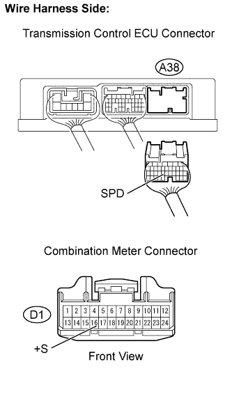
Disconnect the combination meter connector.
Check the resistance.
- Standard resistance:
Tester Connections
Specified Conditions
SPD (A38-23) - +S (D1-16)
Below 1 Ω
SPD (A38-23) or +S (D1-16) - Body ground
10 kΩ or higher
Reconnect the transmission control ECU connector.
Reconnect the combination meter connector.
|
|
||||
| OK | ||
 |
||
| ||