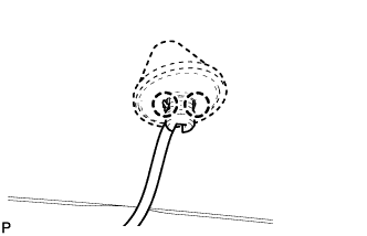
REMOVAL
Removal / installation · Vehicles built from Jan 2006
- NOTICE:
- Always use "Torx" socket wrench E10 when removing the rear seat.
| 1. DISCONNECT CABLE FROM NEGATIVE BATTERY TERMINAL |
| 2. REMOVE PACKAGE TRAY TRIM PANEL ASSEMBLY (w/ Package Tray Trim) |

Remove the 2 package tray trim suspenders.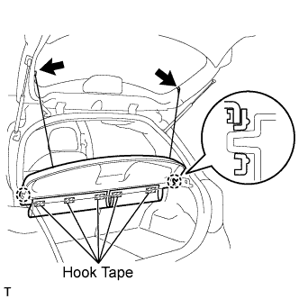

Remove the 5 pieces of hook tape.
Disengage the 2 claws and remove the package tray trim.
| 3. REMOVE DECK BOARD SUB-ASSEMBLY (w/ Deck Board) |
Release the 2 knobs and remove the deck board.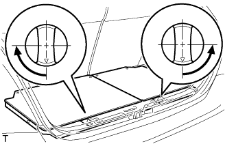
| 4. REMOVE SPARE WHEEL COVER ASSEMBLY (w/ Deck Board) |
Remove the spare wheel cover.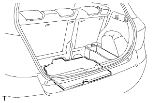
| 5. REMOVE DECK FLOOR BOX RH (w/ Deck Board) |
Release the 2 knobs and remove the deck floor box.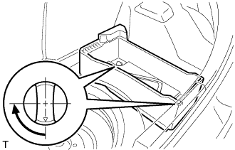
| 6. REMOVE DECK FLOOR BOX LH (w/ Deck Board) |
- HINT:
- Use the same procedure as for the RH side.
| 7. REMOVE REAR FLOOR CARPET ASSEMBLY (w/o Deck Board) |
Remove the rear floor carpet.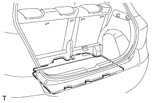
| 8. REMOVE NO. 1 REAR SEAT LEG COVER |
Disengage the 4 claws and remove the No. 1 rear seat leg cover.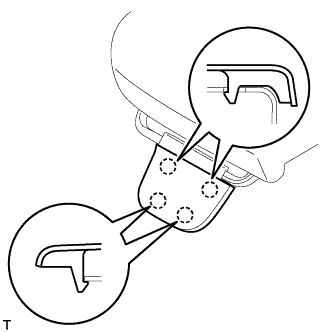
| 9. REMOVE NO. 2 REAR SEAT LEG COVER |
Disengage the 6 claws and remove the No. 2 rear seat leg cover.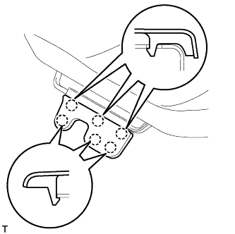
| 10. REMOVE REAR SEAT ASSEMBLY RH |
Using "Torx" socket wrench E10, remove the 2 bolts and pull up the rear seat cushion.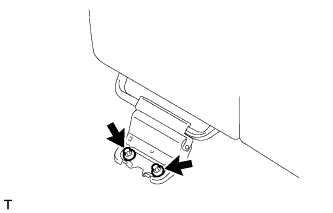
Using "Torx" socket wrench E10, remove the 2 bolts and rear seat.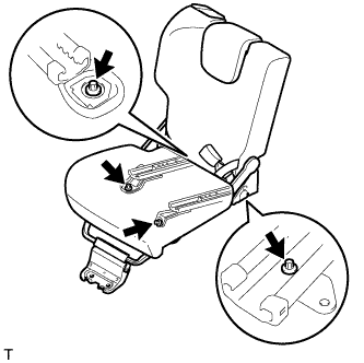
| 11. REMOVE REAR SEAT ASSEMBLY LH |
Using "Torx" socket wrench E10, remove the 3 bolts and pull up the rear seat cushion.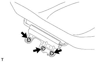
Using "Torx" socket wrench E10, remove the 4 bolts and the rear seat.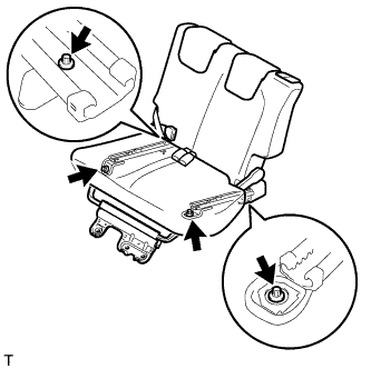
| 12. REMOVE FRONT DOOR SCUFF PLATE RH |
Disengage the 8 claws and remove the front door scuff plate.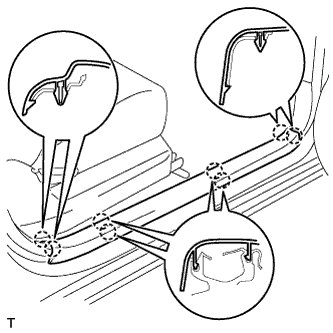
| 13. REMOVE FRONT DOOR SCUFF PLATE LH |
- HINT:
- Use the same procedure as for the RH side.
| 14. REMOVE INSTRUMENT PANEL UNDER COVER SUB-ASSEMBLY RH |
Disengage the 4 claws and remove the instrument panel under cover.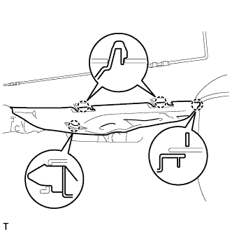
| 15. REMOVE INSTRUMENT PANEL UNDER COVER SUB-ASSEMBLY LH |
Remove the 2 screws.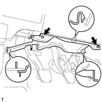
Disengage the 3 claws and remove the instrument panel under cover.
| 16. REMOVE COWL SIDE TRIM BOARD RH |
Disengage the claw and the stud bolt and remove the cowl side trim board.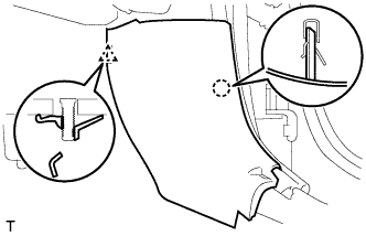
| 17. REMOVE COWL SIDE TRIM BOARD LH |
- HINT:
- Use the same procedure as for the RH side.
| 18. REMOVE FRONT DOOR OPENING TRIM WEATHERSTRIP RH |
Remove the front door opening trim weatherstrip.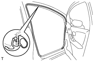
| 19. REMOVE FRONT DOOR OPENING TRIM WEATHERSTRIP LH |
- HINT:
- Use the same procedure as for the RH side.
| 20. REMOVE FRONT SEAT OUTER BELT BAR SUB-ASSEMBLY RH |
Remove the 2 bolts and the front seat outer belt bar.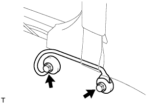
| 21. REMOVE FRONT SEAT OUTER BELT BAR SUB-ASSEMBLY LH |
- HINT:
- Use the same procedure as for the RH side.
| 22. REMOVE FRONT QUARTER TRIM PANEL ASSEMBLY RH |
Remove the belt of the rear seat outer belt from the rear seat shoulder belt hanger.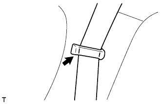
Disengage the 8 clips, the retainer and the 10 claws and remove the front quarter trim panel.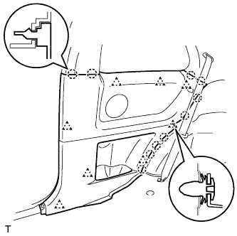
| 23. REMOVE FRONT QUARTER TRIM PANEL ASSEMBLY LH |
- HINT:
- Use the same procedure as for the RH side.
| 24. REMOVE REAR DECK TRIM COVER |
for Grand Tire: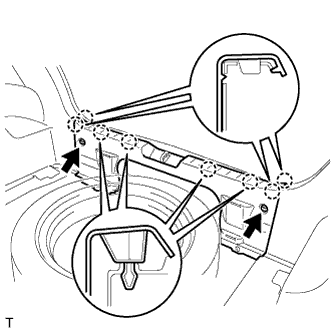
Using a clip remover, remove the 2 clips.
Disengage the 8 claws and remove the rear deck trim cover.
for Temper Spare Tire: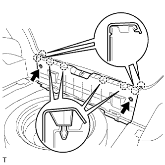
Using a clip remover, remove the 2 clips.
Disengage the 8 claws and remove the rear deck trim cover.
| 25. REMOVE REAR SEAT OUTER BELT ASSEMBLY RH |
Remove the bolt.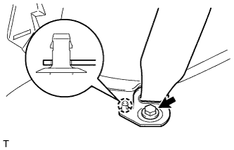
Disengage the clip and remove the anchor plate.
| 26. REMOVE REAR SEAT OUTER BELT ASSEMBLY LH |
- HINT:
- Use the same procedure as for the RH side.
| 27. REMOVE DECK TRIM SIDE PANEL ASSEMBLY RH |
Remove the 3 screws.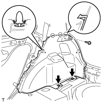
Disengage the 3 clips and the 3 claws and remove the deck side trim panel.
| 28. REMOVE DECK TRIM SIDE PANEL ASSEMBLY LH |
Remove the 3 screws.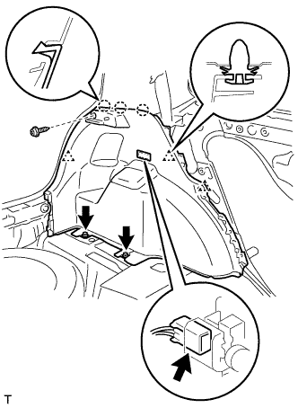
Disengage the 3 clips and the 3 claws.
Disconnect the deck side room light connector and remove the deck side trim panel.
| 29. REMOVE SEAT BELT ANCHOR COVER CAP |
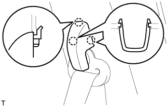 |
- HINT:
- Use the same procedure for both sides.
Disengage the 3 claws and remove the seat belt anchor cover cap.
| 30. REMOVE FRONT SEAT OUTER BELT ASSEMBLY RH |
Remove the bolt and the through anchor.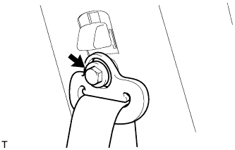
| 31. REMOVE FRONT SEAT OUTER BELT ASSEMBLY LH |
- HINT:
- Use the same procedure as for the RH side.
| 32. REMOVE CENTER PILLAR UPPER GARNISH RH |
Disengage the 2 clips and remove the center pillar garnish.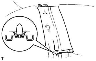
| 33. REMOVE CENTER PILLAR UPPER GARNISH LH |
- HINT:
- Use the same procedure as for the RH side.
| 34. REMOVE REAR CENTER SEAT OUTER BELT ASSEMBLY |
Remove the 2 tongue plates.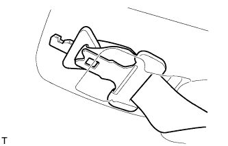
Using a screwdriver with its tip wrapped in protective tape, disengage the 2 claws and open the slip joint cover.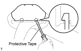
Remove the bolt and the through anchor.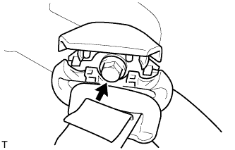
Using a screwdriver with its tip wrapped in protective tape, disengage the 4 claws and remove the center belt guide.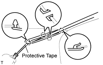
| 35. REMOVE ROOF SIDE INNER GARNISH RH |
w/ Curtain Shield Airbag: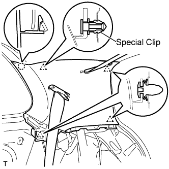
- NOTICE:
- Replace the special clip with a new one when the roof side inner garnish is removed.
Disengage the 4 clips and the claw.
Pass the rear seat outer belt and the rear center seat outer belt through the slit in the roof side inner garnish and remove the roof side inner garnish.
w/o Curtain Shield Airbag: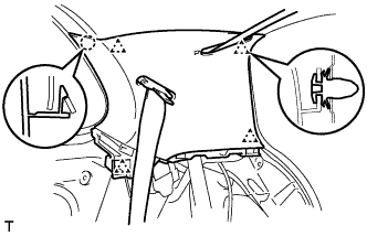
Disengage the 4 clips and the claw.
Pass the rear seat outer belt and the rear center seat outer belt through the slit in the roof side inner garnish and remove the roof side inner garnish.
| 36. REMOVE ROOF SIDE INNER GARNISH LH |
w/ Curtain Shield Airbag: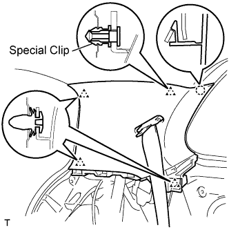
- NOTICE:
- Replace the special clip with a new one when the roof side inner garnish is removed.
Disengage the 4 clips and claw.
Pass the rear seat outer belt through the slit in the roof side inner garnish and remove the roof side inner garnish.
w/o Curtain Shield Airbag: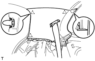
Disengage the 4 clips and claw.
Pass the rear seat outer belt through the slit in the roof side inner garnish and remove the roof side inner garnish.
| 37. REMOVE REAR ROOF SIDE RAIL GARNISH RH |
Disengage the 4 clips and remove the rear roof side rail garnish.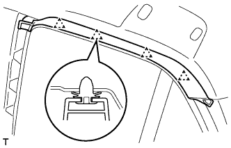
| 38. REMOVE REAR ROOF SIDE RAIL GARNISH LH |
- HINT:
- Use the same procedure as for the RH side.
| 39. REMOVE SEAT BELT ANCHOR COVER |
Using a moulding remover, disengage the 4 claws and remove the seat belt anchor cover.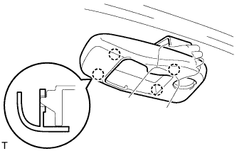
| 40. REMOVE ROOF HEADLINING SERVICE HOLE COVER (w/o Curtain Shield Airbag) |
 |
- HINT:
- The number of the roof headlining service hole covers varies with the specifications.
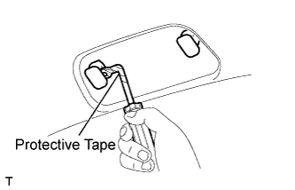
Using a clip remover with its tip wrapped in protective tape, remove the roof headlining service hole cover.
| 41. REMOVE COAT HOOK (w/ Coat Hook) |
Using a screwdriver with its tip wrapped in protective tape, disengage the 2 claws and open the cover.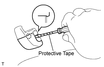
Using a clip remover with its tip wrapped in protective tape, disengage the 2 claws and remove the coat hook.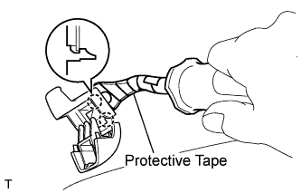
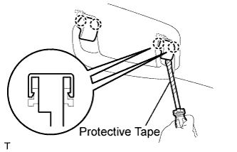
| 42. REMOVE ASSIST GRIP COVER |
 |
- HINT:
- The number of the assist grip covers varies with the specifications.
Using a screwdriver with its tip wrapped in protective tape, disengage the 2 claws and remove the 4 assist grip covers.
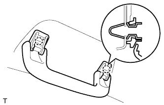
| 43. REMOVE ASSIST GRIP SUB-ASSEMBLY |
 |
- HINT:
- The fitting number of the assist grips varies with the specifications.
Disengage the 2 springs and remove the assist grip.
| 44. REMOVE VISOR ASSEMBLY RH |
Using a screwdriver with its tip wrapped in protective tape, disengage the 4 claws and remove the visor bracket cover.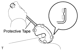
Remove the visor shaft from the visor holder.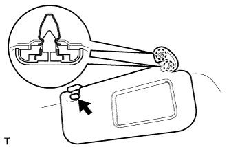
Disengage the 2 springs and remove the visor.
| 45. REMOVE VISOR ASSEMBLY LH |
- HINT:
- Use the same procedure as for the RH side.
| 46. REMOVE VISOR HOLDER RH |
Disengage the 2 claws by turning the visor counterclockwise between 60 to 120° and remove the visor holder.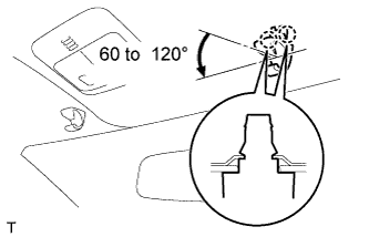
- HINT:
- The claw may be damaged during removal. However, it is reusable because this does not effect its function.
| 47. REMOVE VISOR HOLDER LH |
- HINT:
- Use the same procedure as for the RH side.
| 48. REMOVE ROOM LIGHT ASSEMBLY |
Using a screwdriver with its tip wrapped in protective tape, disengage the 4 claws and remove the room light lens.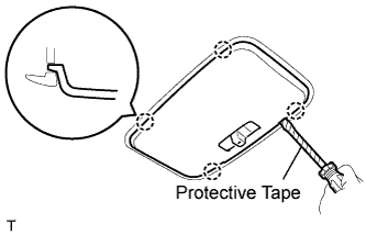
Using a screwdriver with its tip wrapped in protective tape, disengage the 4 claws and remove the 2 covers.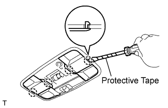
Using a screwdriver with its tip wrapped in protective tape, disengage the 4 claws and remove the room light.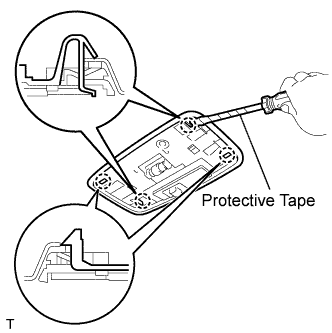
Remove the roof wire from the claw of the room light.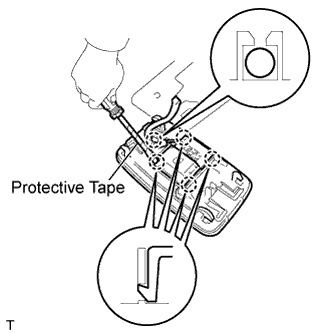
Using a screwdriver with its tip wrapped in protective tape, disengage the 4 claws and remove the room light switch base.
| 49. REMOVE MAP LIGHT ASSEMBLY |
Using a roof moulding remover, disengage the 4 claws and remove the map light.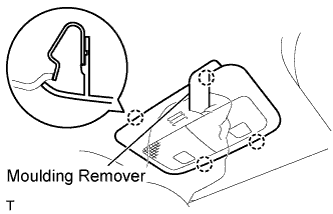
Disconnect the map light connector.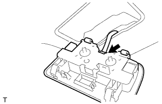
| 50. REMOVE FRONT PILLAR GARNISH RH |
w/ Curtain Shield Airbag: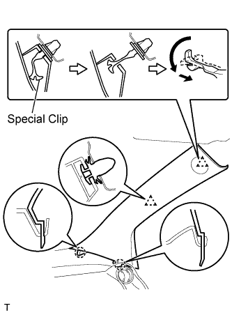
- NOTICE:
- Install a protective cover onto the curtain shield airbag as soon as the front pillar garnish is removed.
- Replace the special clip with a new one when the front pillar garnish is removed.
- Install a protective cover onto the curtain shield airbag as soon as the front pillar garnish is removed.
Disengage the 2 clips and the 2 claws and remove the front pillar garnish.
w/o Curtain Shield Airbag: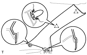
Disengage the 2 clips and the 2 claws and remove the front pillar garnish.
Disconnect the connector.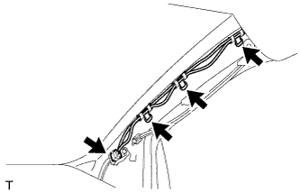
Using a clip remover, remove the 3 antenna cord clamps.
Disconnect the speaker connector.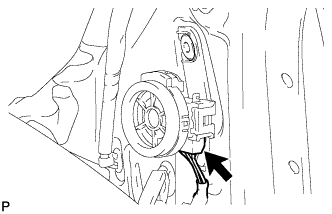
Using a screwdriver with its tip wrapped in protective tape, disengage the clip and hook and remove the front No. 2 speaker.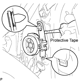
w/ Curtain Shield Airbag: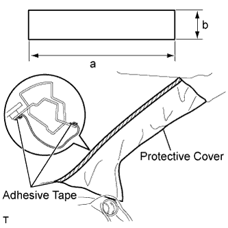
Completely cover the curtain shield airbag with a piece of cloth or nylon and fix the ends of the fabric with adhesive tape, as shown in the illustration.
Protective cover size: Area
Measurement
a
700 mm (27.56 in.)
b
120 mm (4.72 in.)
| 51. REMOVE FRONT PILLAR GARNISH LH |
w/ Curtain Shield Airbag: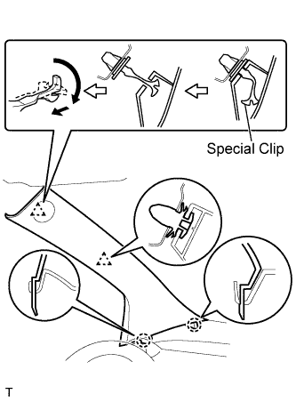
- NOTICE:
- Install a protective cover onto the curtain shield airbag as soon as the front pillar garnish is removed.
- Replace the special clip with a new one when the front pillar garnish is removed.
- Install a protective cover onto the curtain shield airbag as soon as the front pillar garnish is removed.
Disengage the 2 clips and the 2 claws and remove the front pillar garnish.
w/o Curtain Shield Airbag: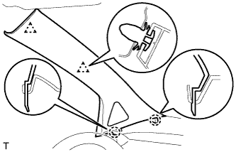
Disengage the 2 clips and the 2 claws and remove the front pillar garnish.
Using a clip remover, remove the 4 wiring harness clamps.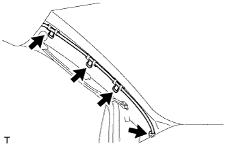
Disconnect the speaker connector.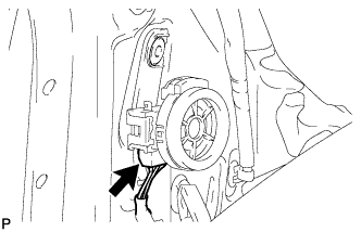
Using a screwdriver with its tip wrapped in protective tape, disengage the clip and hook and remove the front No. 2 speaker.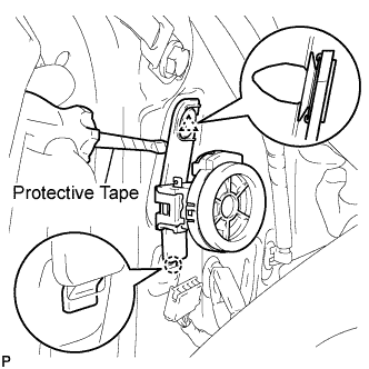
w/ Curtain Shield Airbag: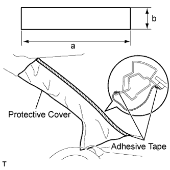
Completely cover the curtain shield airbag with a piece of cloth or nylon and fix the ends of the fabric with adhesive tape, as shown in the illustration.
Protective cover size: Area
Measurement
a
700 mm (27.56 in.)
b
120 mm (4.72 in.)
| 52. REMOVE ROOF HEADLINING ASSEMBLY |
Remove the antenna cord from the antenna cord clamp.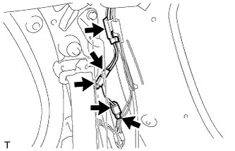
Disconnect the 2 connectors.
Using a clip remover, remove the 2 connectors.
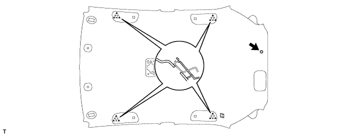
w/ Curtain Shield Airbag:
Using a clip remover, remove the clip.
Disengage the 4 hooks and remove the roof headlining.
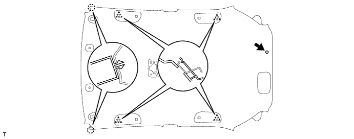
w/o Curtain Shield Airbag:
Using a clip remover, remove the clip.
Disengage the 2 claws and the 4 hooks and remove the roof headlining.
| 53. REMOVE ROOF ANTENNA POLE SUB-ASSEMBLY |
Remove the roof antenna pole by turning it in the direction of the arrow shown in the illustration.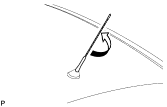
| 54. REMOVE AMPLIFIER ANTENNA ASSEMBLY |
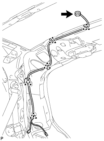 |
Disengage the 5 clamps.
Remove the antenna nut.
Disengage the 2 claws and remove the amplifier antenna.