REASSEMBLY
Removal / installation · Vehicles built from Aug 2005
| 1. INSTALL DIRECT CLUTCH DRUM O-RING |

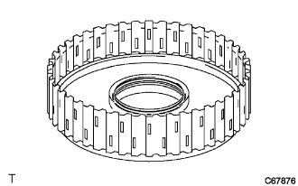  |
Coat a new O-ring with ATF and install it into the direct clutch drum.
- NOTICE:
- Do not damage the O-rings.
| 2. INSTALL DIRECT CLUTCH PISTON O-RING |
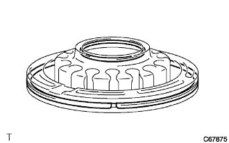 |
Coat 2 new O-rings with ATF and install them into the direct clutch piston.
- NOTICE:
- Do not damage the O-rings.
| 3. INSTALL DIRECT CLUTCH DRUM SUB-ASSEMBLY |
Coat the direct clutch drum with ATF.
Align the cutout in the intermediate shaft assembly with the matchmark on the direct clutch drum and install the direct clutch drum onto the intermediate shaft assembly.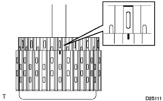
- NOTICE:
- Do not damage the O-ring or the lip of the clutch drum.
| 4. INSTALL DIRECT CLUTCH PISTON SUB-ASSEMBLY |
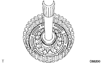 |
Coat the direct clutch piston with ATF and install it into the intermediate shaft.
- NOTICE:
- Do not damage the O-ring or the direct clutch piston.
| 5. INSTALL DIRECT CLUTCH RETURN SPRING SUB-ASSEMBLY |
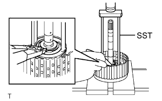 |
Install the direct clutch return spring onto the direct clutch piston.
Place SST on the piston return spring and compress the springs with a press.
- SST
- 09387-00020
Using snap ring pliers, install the snap ring into the direct clutch drum.
- NOTICE:
- Stop pressing the press when the spring seat is lowered to 1 to 2 mm (0.039 to 0.078 in.) from the snap ring groove to prevent the spring seat from deforming.
- Do not expand the snap ring excessively.
- Stop pressing the press when the spring seat is lowered to 1 to 2 mm (0.039 to 0.078 in.) from the snap ring groove to prevent the spring seat from deforming.
| 6. INSTALL DIRECT CLUTCH DISC |
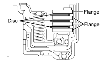 |
Coat the 3 rear clutch flanges, 3 discs and direct clutch flange with ATF and install them onto the intermediate shaft.
Install the snap ring into the intermediate shaft.
| 7. INSTALL REVERSE CLUTCH DISC |
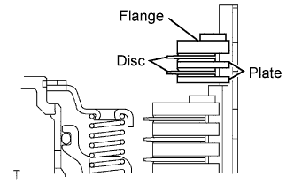 |
Coat the 2 plates, 2 discs and flange with ATF, and install them onto the intermediate shaft.
Install the snap ring into the intermediate shaft.
| 8. INSPECT PACK CLEARANCE OF REVERSE CLUTCH |
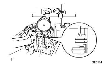 |
Install the intermediate shaft and thrust needle roller bearing onto the transaxle rear cover.
Using a dial indicator, measure the reverse clutch pack clearance while applying and releasing compressed air (392 kPa, 4.0 kgf/cm2, 57 psi).
- Pack clearance:
- 0.86 to 1.26 mm (0.0339 to 0.0496 in.)
- NOTICE:
- If the clearance is outside the specifications, select a new brake flange.
- HINT:
- There are 4 different flange thicknesses.
- Flange thickness:
No.
Thickness mm (in.)
No.
Thickness mm (in.)
-
3.0 (0.118)
2
3.4 (0.134)
1
3.2 (0.126)
3
3.6 (0.142)
| 9. INSPECT PACK CLEARANCE OF DIRECT CLUTCH |
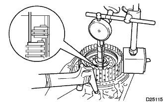 |
Install the intermediate shaft and thrust needle roller bearing onto the transaxle rear cover.
Using a dial indicator and measuring terminal (SST), measure the forward clutch pack clearance while applying and releasing compressed air (392 kPa, 4.0 kgf/cm2, 57 psi).
- SST
- 09350-36010
(09350-06110)
- HINT:
- The direct and reverse clutch will come out as the compressed air is applied.
- Therefore, while performing the check, press on the input shaft of the direct and reverse clutch using a stamping machine or the equivalent so that the pressure is not applied to the direct and reverse clutch.
- Pack clearance:
- 0.62 to 1.02 mm (0.0244 to 0.0402 in.)
- NOTICE:
- If the clearance is outside the specifications, select a new brake flange.
- HINT:
- There are 4 different flange thicknesses.
- Flange thickness:
No.
Thickness mm (in.)
No.
Thickness mm (in.)
-
3.0 (0.118)
2
3.4 (0.134)
1
3.2 (0.126)
3
3.6 (0.142)