INSTALLATION
Removal / installation · Vehicles built from Jan 2006
| 1. TEMPORARILY TIGHTEN FRONT SHOCK ABSORBER WITH COIL SPRING |

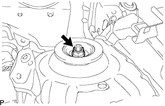  |
Provisionally tighten a new nut through No. 2 suspension support.
Install the front shock absorber with coil spring onto the steering knuckle.
Install the 2 bolts and 2 nuts.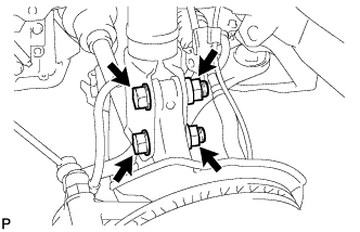
- Torque:
- 164 N*m{ 1,672 kgf*cm , 121 ft.*lbf }
- HINT:
- Keep the bolt from rotating while loosening and removing the nuts.
| 2. INSTALL FRONT FLEXIBLE HOSE |
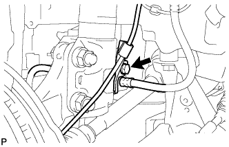 |
w/ ABS:
Install the flexible hose and speed sensor with the bolt.
- Torque:
- 29 N*m{ 300 kgf*cm , 22 ft.*lbf }
- NOTICE:
- Install the flexible hose and speed sensor without twisting them.
w/o ABS:
Install the flexible hose with the bolt.
- Torque:
- 29 N*m{ 300 kgf*cm , 22 ft.*lbf }
- NOTICE:
- Install the flexible hose without twisting them.
| 3. INSTALL FRONT STABILIZER LINK ASSEMBLY |
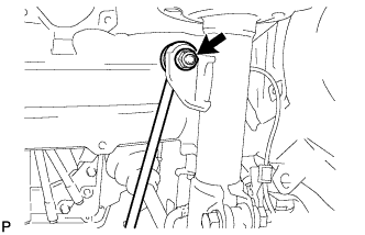 |
Install the stabilizer link with the nut.
- Torque:
- 74 N*m{ 755 kgf*cm , 55 ft.*lbf }
- HINT:
- If the ball joint turns together with the nut, use a socket hexagon wrench 6 to hold the stud.
| 4. INSTALL FRONT WHEEL |
- Torque:
- 103 N*m{ 1,050 kgf*cm , 76 ft.*lbf }
| 5. FULLY TIGHTEN FRONT SHOCK ABSORBER WITH COIL SPRING |
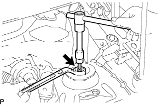 |
Using a socket hexagon wrench 6, fix the shock absorber rod and tighten the nut.
- Torque:
- 55 N*m{ 561 kgf*cm , 41 ft.*lbf }
| 6. INSTALL FRONT SUSPENSION SUPPORT DUST COVER |
| 7. INSTALL COWL TOP PANEL OUTER |
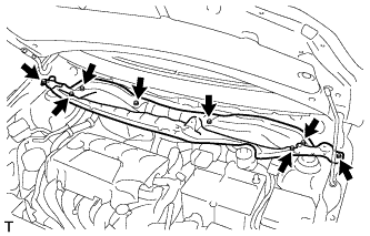 |
Install the cowl top panel outer with the 8 bolts.
- Torque:
- 6.5 N*m{ 66 kgf*cm , 57 in.*lbf }
Install the cowl top to cowl inner brace with the 2 bolts.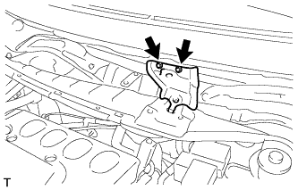
- Torque:
- 6.5 N*m{ 66 kgf*cm , 57 in.*lbf }
Connect the wire harness clamp.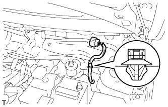
| 8. INSTALL FRONT AIR SHUTTER SEAL |
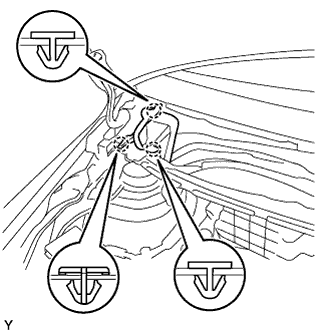 |
Engage the 3 claws to install the front air shutter seal.
| 9. INSTALL FRONT WIPER MOTOR AND LINK |
Connect the connector.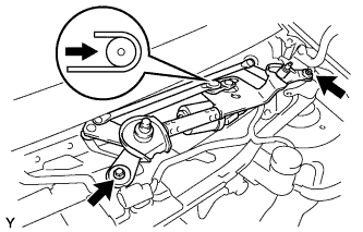
Slide the wiper link as shown in the illustration and engage the rubber pin with the body.
Install the front wiper motor and link with the 2 bolts.
- Torque:
- 5.5 N*m{ 56 kgf*cm , 49 in.*lbf }
| 10. INSTALL COWL TOP VENTILATOR LOUVER SUB-ASSEMBLY (for LHD) |
Connect the washer hoses.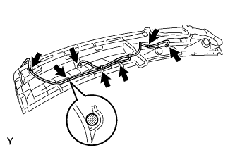
Engage the 5 hooks.
Engage the 8 hooks and the 4 claws.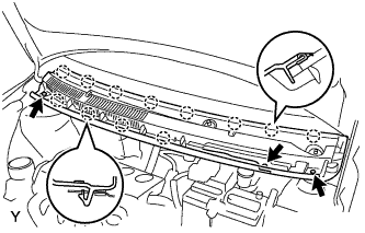
Install the cowl top ventilator louver sub-assembly with the 3 clips.
| 11. INSTALL COWL TOP VENTILATOR LOUVER SUB-ASSEMBLY (for RHD) |
Connect the washer hoses.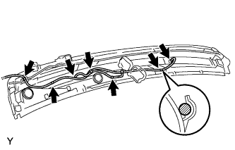
Engage the 5 hooks.
Engage the 10 hooks and the 6 claws.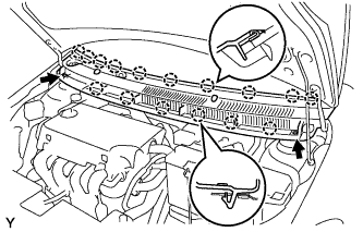
Install the cowl top ventilator louver sub-assembly with the 2 clips.
| 12. INSTALL COWL SIDE VENTILATOR SUB-ASSEMBLY LH |
Engage the 3 claws and install the cowl side ventilator sub-assembly LH.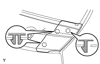
| 13. INSTALL COWL SIDE VENTILATOR SUB-ASSEMBLY RH |
- HINT:
- Use the same procedure as for the LH side.
| 14. INSTALL FRONT WIPER ARM AND BLADE ASSEMBLY LH |
Scrape any metal powder off the serrated part of the wiper arm with a round file or the equivalent (when reinstalling).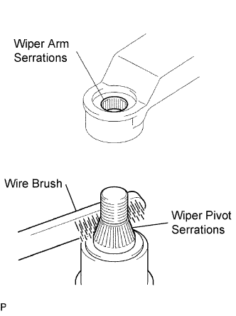
Clean the wiper pivot serrations with a wire brush.
Operate the wiper, then stop the windshield wiper motor in the automatic stop position.
Align the blade tip with the mark on the windshield glass, as shown in the illustration.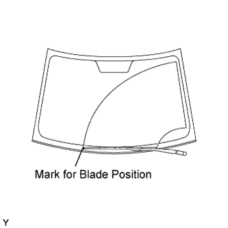
Tighten the nut of the front wiper arm.
- Torque:
- 26 N*m{ 265 kgf*cm , 19 ft.*lbf }
| 15. INSTALL FRONT WIPER ARM AND BLADE ASSEMBLY RH |
Scrape any metal powder off the serrated part of the wiper arm with a round file or the equivalent (when reinstalling).
Clean the wiper pivot serrations with a wire brush.
Operate the wiper, then stop the windshield wiper motor in the automatic stop position.
Align the blade tip with the mark on the windshield glass, as shown in the illustration.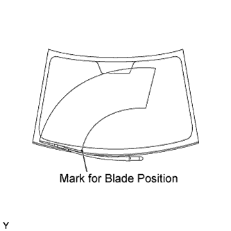
Tighten the nut of the front wiper arm.
- Torque:
- 26 N*m{ 265 kgf*cm , 19 ft.*lbf }
| 16. INSTALL FRONT WIPER ARM HEAD CAP |
Engage the claw and install the 2 front wiper arm head caps.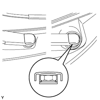
| 17. CONNECT CABLE TO NEGATIVE BATTERY TERMINAL |
- Torque:
- 5.4 N*m{ 55 kgf*cm , 48 in.*lbf }
| 18. INSPECT AND ADJUST FRONT WHEEL ALIGNMENT |