REMOVAL
Removal / installation · Vehicles built from Nov 2005
| 1. DISCONNECT CABLE FROM NEGATIVE BATTERY TERMINAL |
| 2. REMOVE REAR WHEEL |
| 3. REMOVE REAR BRAKE DRUM SUB-ASSEMBLY (for Rear Drum Brake) |

Release the parking brake and remove the rear brake drum.
If the rear brake drum cannot be removed easily, perform the following procedure.
for Manual Transaxle:
Remove the shift lever knob.
Remove the shifting hole cover (Click here).
Remove the console box rear cover (Click here).
Remove the console box carpet (Click here).
Remove the rear console box (Click here).
Loosen the wire adjusting nut.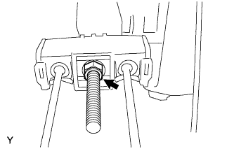

- NOTICE:
- Do not reuse the loosened nut.
Remove the hole plug.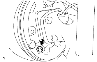
Insert SST through the hole in the backing plate, pull the parking brake shoe lever toward the rear of the vehicle and remove the rear brake drum.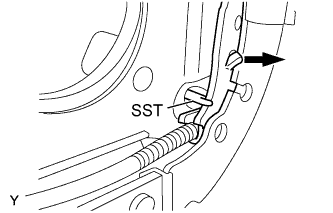
- SST
- 09921-00010
| 4. DISCONNECT PARKING BRAKE CABLE ASSEMBLY (for Rear Disc Brake) |
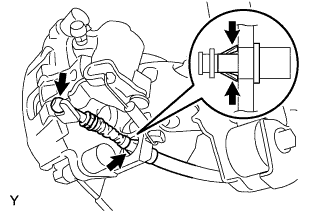 |
Disconnect the cable end from the rear disc brake cylinder operation lever.
Using needle-nose pliers, disengage the claws of the casing cap and disconnect the parking brake cable.
| 5. SEPARATE REAR DISC BRAKE CALIPER ASSEMBLY (for Rear Disc Brake) |
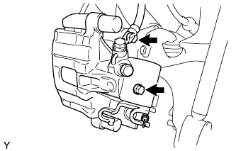 |
Remove the 2 bolts and separate the disc brake caliper from the rear axle beam.
- NOTICE:
- Hang the caliper using a piece of string or the equivalent
| 6. REMOVE REAR DISC (for Rear Disc Brake) |
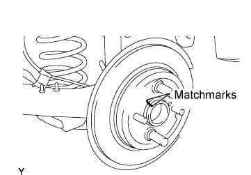 |
Place matchmarks on the disc and axle hub and remove the disc.
| 7. DISCONNECT SKID CONTROL SENSOR WIRE |
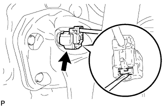 |
Using a screwdriver, remove the claw of the connector lock portion and disconnect the skid control sensor wire connector.
- NOTICE:
- Do not remove the connector cover from the connector because the skid control sensor wire may be damaged.
| 8. REMOVE REAR AXLE HUB AND BEARING ASSEMBLY |
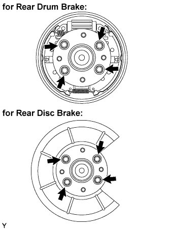 |
for Rear Drum Brake:
Remove the 4 bolts and remove the axle hub and bearing from the axle beam.
- NOTICE:
- Suspend the backing plate with a piece of rope.
for Rear Disc Brake:
Remove the 4 bolts and remove the axle hub and bearing and the dust cover from the axle beam.
| 9. REMOVE SKID CONTROL SENSOR |
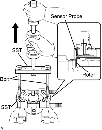 |
Install the 4 hub nuts and the 4 hub bolts onto the rear axle hub, and then fix the rear axle hub in a vise between aluminum plates.
- NOTICE:
- If the skid control sensor is dropped or heavily damaged, replace the rear axle hub and bearing.
Using a 3 mm pin punch and hammer, remove the 2 pins from SST (09520-00031) and remove the attachment (09521-00010).
Using SST and the 2 bolts (90101-12007), remove the skid control sensor from the rear axle hub.
- SST
- 09520-00031
(09520-00040)
09521-00020
09950-00020
- NOTICE:
- Pull the skid control sensor off straight, being careful not to bring it into contact with the skid control sensor rotor.
- If the skid control sensor rotor is damaged or deformed, replace the rear axle hub and bearing.
- Do not damage the skid control sensor or rear axle hub contact surfaces.
- Keep the sensor rotor free of foreign matter.
- Pull the skid control sensor off straight, being careful not to bring it into contact with the skid control sensor rotor.