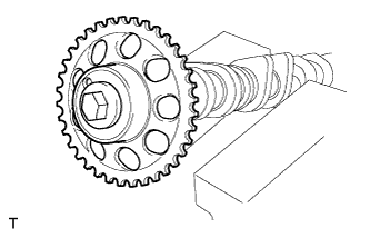
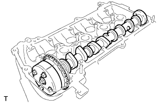
Install the camshaft timing gear assembly onto the camshaft with the lock pin of the camshaft timing gear assembly released.
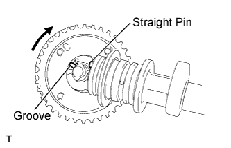
Put the camshaft timing gear assembly and camshaft together with the straight pin of the groove.
Turn the camshaft timing gear assembly clockwise while pushing it gently toward the camshaft. Push further at the position where the pin fits into the groove.
NOTICE:
Do not turn the camshaft timing gear to the retard angle (to the right).
Check that there is no clearance between the gear flange and the camshaft.
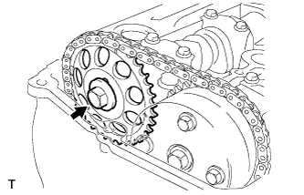
Tighten the flange bolt with the camshaft timing gear fixed.
Torque:
64 N*m{
653 kgf*cm
, 47 ft.*lbf
}
NOTICE:
Do not lock the camshaft timing gear assembly when tightening the bolt.
Release the lock pin of the camshaft timing gear assembly first, and tighten the bolt when the lock pin is locked in the most retarded position.
Tightening the bolts with the lock pin locked could cause breakage of the lock pin.
Check that the camshaft timing gear assembly can move to the retard angle (to the right) and is locked in the most retarded position.
3.
INSTALL CAMSHAFT
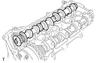
Apply a light coat of engine oil to the camshaft and camshaft journals.
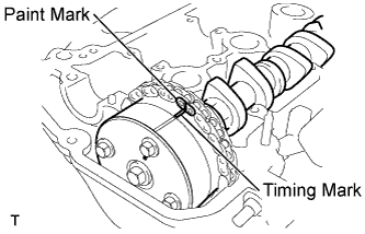
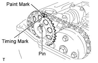
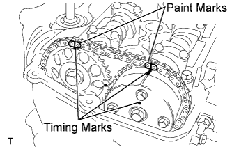
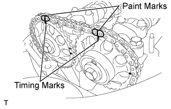
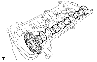
for Unleaded Gasoline Specification Vehicle: Install the chain onto the camshaft timing gear with the paint mark and the timing mark aligned as shown in the illustration.
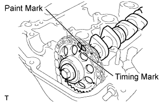
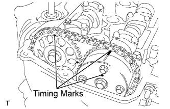
for Leaded Gasoline Specification Vehicle: Install the chain onto the camshaft timing sprocket with the paint mark and the timing mark aligned as shown in the illustration.
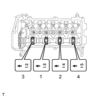
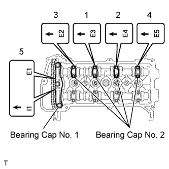
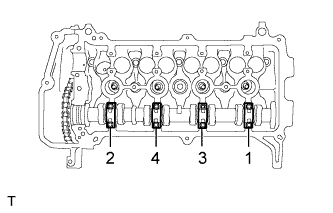
Examine the front marks and numbers on camshaft bearing cap No. 2 and check that the sequence is as shown in the illustration. Then uniformly tighten the bolts, in several steps, in the sequence shown in the illustration.
Torque:
13 N*m{
129 kgf*cm
, 9.4 ft.*lbf
}
NOTICE:
Tighten each bolt uniformly while keeping the camshaft level.
4.
INSTALL NO. 2 CAMSHAFT
Install camshaft No. 2.
Hold the chain and align the timing mark on the camshaft timing sprocket with the paint mark of the chain.
Align the alignment pin hole in the camshaft timing sprocket with the alignment pin of the camshaft, and install the sprocket onto the camshaft.
Provisionally install the flange bolt.
Examine the front marks and numbers on camshaft bearing caps No. 1 and No. 2 and check that the sequence is as shown in the illustration. Then uniformly tighten the bolts, in several steps, in the sequence shown in the illustration.
Torque:
for bearing cap No. 2:
13 N*m{
129 kgf*cm
, 9.4 ft.*lbf
}
for bearing cap No. 1:
23 N*m{
235 kgf*cm
, 17 ft.*lbf
}
NOTICE:
Tighten each bolt uniformly while keeping the camshaft level.
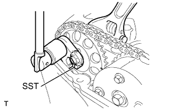
Using a wrench, hold the hexagonal lobe of camshaft No. 2 and install the flange bolt.
Torque:
64 N*m{
653 kgf*cm
, 47 ft.*lbf
}
SST
09023-38400
Remove the bar from the timing chain tensioner.
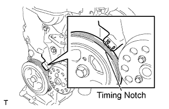
Turn the crankshaft damper and align its timing notch with the timing mark "0" of the oil pump.
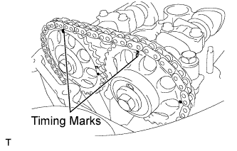
for Unleaded Gasoline Specification Vehicle: Check that all the pairs of timing marks are aligned.
for Leaded Gasoline Specification Vehicle: Check that all the pairs of timing marks are aligned.
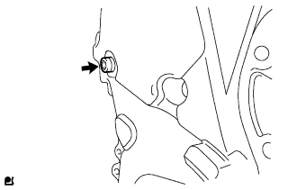
Apply adhesive to 2 or 3 threads of the screw plug end.
Adhesive:
Part No. 08833-00070, THREE BOND 1324 or the equivalent
Using an 8 mm hexagon wrench, install the screw plug.
Torque:
15 N*m{
153 kgf*cm
, 11 ft.*lbf
}
5.
INSPECT VALVE CLEARANCE
HINT:
Inspect the valve clearance when the engine is cold.
Set No.1 cylinder to TDC/compression.
Turn the crankshaft damper and align its timing notch with the timing mark "0" of the oil pump.
for Unleaded Gasoline Specification Vehicle: Check that both timing marks on the camshaft timing sprocket and camshaft timing gear are facing upward, as shown in the illustration.
HINT:
If not, turn the crankshaft 1 complete revolution (360°) and align the marks as above.
for Leaded Gasoline Specification Vehicle: Check that both timing marks on the camshaft timing sprockets facing upward as shown in the illustration.
HINT:
If not, turn the camshaft 1 complete revolution (360°) and align the marks as above.
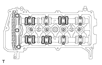
Check the valves indicated in the illustration.
Using a feeler gauge, measure the clearance between the valve lifter and camshaft.
Valve clearance (cold):
for intake:
0.15 to 0.25 mm (0.006 to 0.010 in.)
for exhaust:
0.25 to 0.35 mm (0.010 to 0.014 in.)
Record any out-of-specification valve clearance measurements. They will be used later to determine the required replacement adjusting shim.
Turn the crankshaft 1 complete revolution (360°) and align its timing notch with the timing mark "0" of the oil pump.
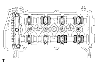
Check the valves indicated in the illustration.
Using a feeler gauge, measure the clearance between the valve lifter and camshaft.
Valve clearance (cold):
for intake:
0.15 to 0.25 mm (0.006 to 0.010 in.)
for exhaust:
0.25 to0.35 mm (0.010 to 0.014 in.)
Record any out-of-specification valve clearance measurements. They will be used later to determine the required replacement adjusting shim.
6.
ADJUST VALVE CLEARANCE
NOTICE:
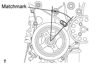
When rotating the camshaft with the timing chain removed, rotate the crankshaft damper counterclockwise 40° from the TDC and align its timing notch with the matchmark of the timing chain cover to prevent the pistons from coming into contact with the valves.
Remove the engine mounting insulator sub-assembly RH (Click here).
Set No. 1 cylinder to TDC/compression.
Turn the crankshaft damper and align its timing notch with the timing mark "0" of the oil pump.
for Unleaded Gasoline Specification Vehicle: Check that both timing marks on the camshaft timing sprocket and camshaft timing gear are facing upward, as shown in the illustration.
HINT:
If not, turn the crankshaft 1 complete revolution (360°) and align the marks as above.
for Leaded Gasoline Specification Vehicle: Check that both timing marks on the camshaft timing sprockets facing upward as shown in the illustration.
HINT:
If not, turn the crankshaft 1 complete revolution (360°) and align the marks as above.
for Unleaded Gasoline Specification Vehicle: Place paint marks on the chain in the places where the timing marks of the camshaft timing sprocket and the camshaft timing gear are located.
for Leaded Gasoline Specification Vehicle: Place paint marks on the chain in the places where the timing marks of the camshaft timing sprockets are located.
Using an 8 mm hexagon wrench, remove the screw plug.
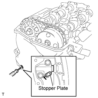
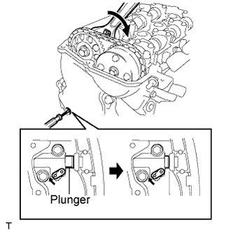
Insert a screwdriver into the service hole in the chain tensioner to pull the stopper plate of the chain tensioner upward.
Using a wrench, rotate camshaft No. 2 clockwise to push in the plunger of the chain tensioner.
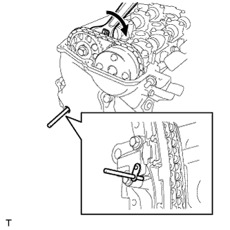
Remove the screwdriver from the service hole, then align the hole of the stopper plate with the service hole and insert a 3 mm (0.12 in.) diameter bar into the holes to hold the stopper plate.
HINT:
Fix the stopper plate using the bar while rotating the camshaft right and left slightly.
Hold the bar with tape so that the bar does not come off.
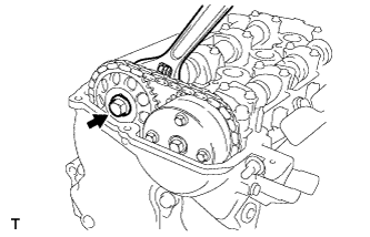
Using a wrench, hold the hexagonal lobe of camshaft No. 2 and remove the fringe bolt.
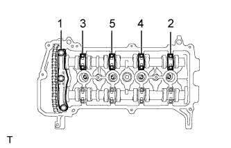
Using several steps, loosen and remove the 11 bearing cap bolts uniformly in the sequence shown in the illustration, then remove camshaft bearing cap No. 1 and camshaft bearing cap No. 2.
NOTICE:
Loosen each bolt uniformly while keeping the camshaft level.
Remove the fringe bolt and remove the camshaft timing sprocket.
Remove camshaft No. 2.
Using several steps, loosen and remove the 8 bearing cap bolts uniformly in the sequence shown in the illustration, then remove camshaft bearing cap No. 2.
NOTICE:
Loosen each bolt uniformly while keeping the camshaft level.
for Unleaded Gasoline Specification Vehicle: Hold the chain by hand, and remove the camshaft and the camshaft timing gear assembly.
for Leaded Gasoline Specification Vehicle: Hold the chain by hand, and remove the camshaft and the camshaft timing sprocket.
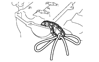
Tie the chain with a piece of string as shown in the illustration.
Remove the valve lifters.
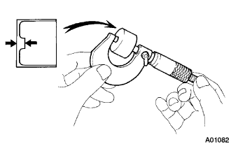
Using a micrometer, measure the thickness of the removed lifter.
Calculate the thickness of a new lifter so that the valve clearance comes to within the specified values.
A
Thickness of new lifter
B
Thickness of used lifter
C
Measured valve clearance
Valve clearance:
Intake A = B + (C - 0.20mm (0.008in.))
Exhaust A = B + (C - 0.30mm (0.012in))
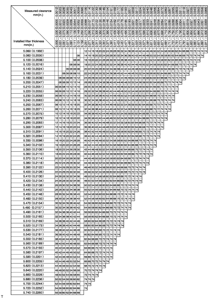
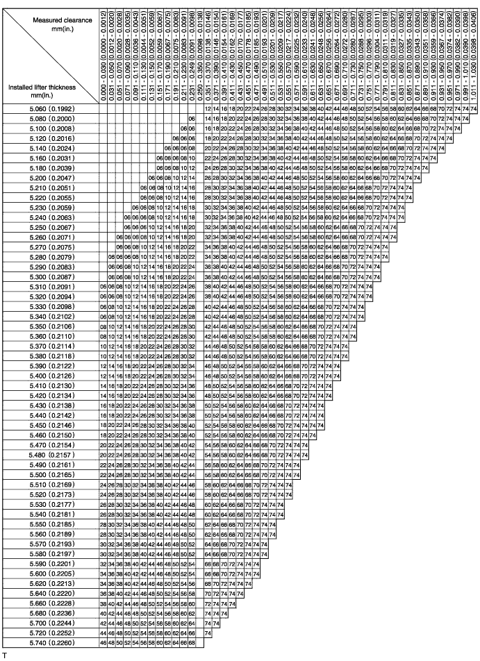
Select a new lifter with a thickness as close to the calculated values as possible.
HINT:
Lifters are available in 35 sizes in increments of 0.020mm (0.0008 in.), from 5.060 mm (0.1992 in.) to 5.740 mm (0.2260 in.).
Intake valve clearance (cold):
0.15 to 0.25 mm (0.006 to 0.010 in.)
EXAMPLE:
A 5.250 mm (0.2067 in.) lifter is installed, and the measured clearance is 0.400 mm (0.0158 in.). Replace the 5.250 mm (0.2067 in.) lifter with a new No. 46 lifter.
New Shim Thickness:
Shim No.
Thickness
Shim No.
Thickness
Shim No.
Thickness
06
5.060 (0.1992)
30
5.300 (0.2087)
54
5.540 (0.2181)
08
5.080 (0.2000)
32
5.320 (0.2094)
56
5.560 (0.2189)
10
5.100 (0.2008)
34
5.340 (0.2102)
58
5.580 (0.2197)
12
5.120 (0.2016)
36
5.360 (0.2110)
60
5.600 (0.2205)
14
5.140 (0.2024)
38
5.380 (0.2118)
62
5.620 (0.2213)
16
5.160 (0.2031)
40
5.400 (0.2126)
64
5.640 (0.2220)
18
5.180 (0.2039)
42
5.420 (0.2134)
66
5.660 (0.2228)
20
5.200 (0.2047)
44
5.440 (0.2142)
68
5.680 (0.2236)
22
5.220 (0.2055)
46
5.460 (0.2150)
70
5.700(0.2244)
24
5.240 (0.2063)
48
5.480 (0.2157)
72
5.720 (0.2252)
26
5.260 (0.2071)
50
5.500 (0.2165)
74
5.740 (0.2260)
28
5.280 (0.2079)
52
5.520 (0.2173)
Exhaust valve clearance (Cold):
0.25 to 0.35 mm (0.010 to 0.014 in.)
EXAMPLE:
A 5.340 mm (0.2102 in.) lifter is installed, and the measured clearance is 0.440 mm (0.0173 in.). Replace the 5.340 mm (0.2102 in.) lifter with a new No. 48 lifter.
New Shim Thickness:
Shim No.
Thickness
Shim No.
Thickness
Shim No.
Thickness
06
5.060 (0.1992)
30
5.300 (0.2087)
54
5.540 (0.2181)
08
5.080 (0.2000)
32
5.320 (0.2094)
56
5.560 (0.2189)
10
5.100 (0.2008)
34
5.340 (0.2102)
58
5.580 (0.2197)
12
5.120 (0.2016)
36
5.360 (0.2110)
60
5.600 (0.2205)
14
5.140 (0.2024)
38
5.380 (0.2118)
62
5.620 (0.2213)
16
5.160 (0.2031)
40
5.400 (0.2126)
64
5.640 (0.2220)
18
5.180 (0.2039)
42
5.420 (0.2134)
66
5.660 (0.2228)
20
5.200 (0.2047)
44
5.440 (0.2142)
68
5.680 (0.2236)
22
5.220 (0.2055)
46
5.460 (0.2150)
70
5.700 (0.2244)
24
5.240 (0.2063)
48
5.480 (0.2157)
72
5.720 (0.2252)
26
5.260 (0.2071)
50
5.500 (0.2165)
74
5.740 (0.2260)
28
5.280 (0.2079)
52
5.520 (0.2173)
Install the selected valve lifter.
Apply a light coat of engine oil to the camshaft and camshaft journals.
for Unleaded Gasoline Specification Vehicle: Install the chain onto the camshaft timing gear with the paint mark and the timing mark aligned as shown in the illustration.
for Leaded Gasoline Specification Vehicle: Install the chain onto the camshaft timing sprocket with the paint mark and the timing mark aligned as shown in the illustration.
Examine the front marks and the numbers on camshaft bearing cap No. 2 and check that the sequence order is as shown in the illustration. Then uniformly tighten the bolts in several steps in the sequence shown in the illustration.
Torque:
13 N*m{
129 kgf*cm
, 9.4 ft.*lbf
}
NOTICE:
Tighten each bolt uniformly while keeping the camshaft level.
Install camshaft No. 2.
Hold the chain, and align the timing mark on the camshaft timing sprocket with the paint mark of the chain.
Align the alignment pin hole in the camshaft timing sprocket with the alignment pin of the camshaft, and install the sprocket onto the camshaft.
Provisionally install the flange bolt.
Examine the front marks and the numbers of camshaft bearing cap No. 1 and camshaft bearing cap No. 2 and check that the sequence order is as shown in the illustration. Then uniformly tighten the bolts in several steps, in the sequence shown in the illustration.
Torque:
for bearing cap No. 2:
13 N*m{
129 kgf*cm
, 9.4 ft.*lbf
}
for bearing cap No. 1:
23 N*m{
235 kgf*cm
, 17 ft.*lbf
}
NOTICE:
Tighten each bolt uniformly while keeping the camshaft level.
Using a wrench, hold the hexagonal lobe of camshaft No. 2 and install the flange bolt.
Torque:
64 N*m{
653 kgf*cm
, 47 ft.*lbf
}
SST
09023-38400
Remove the bar from the timing chain tensioner.
Turn the crankshaft damper and align its timing notch with the timing mark "0" of the oil pump.
for Unleaded Gasoline Specification Vehicle: Check that all the pairs of timing marks are aligned.
for Leaded Gasoline Specification Vehicle: Check that all the pairs of the timing marks are aligned.
Apply adhesive to 2 or 3 threads of the screw plug end.
Adhesive:
Part No. 08833-00070, THREE BOND 1324 or the equivalent
Using an 8 mm hexagon wrench, install the screw plug.
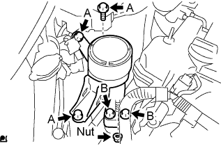
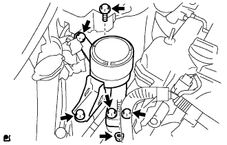
Install the engine mounting insulator sub-assembly RH with the 5 bolts and nut.
Torque:
52 N*m{
530 kgf*cm
, 38 ft.*lbf
}
9.
INSTALL FAN AND GENERATOR V BELT
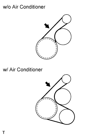
Provisionally install the fan and generator V belt onto each pulley.
NOTICE:
Make sure that the V-belt is securely fitted into the rib groove of the pulley.
10.
ADJUST FAN AND GENERATOR V BELT
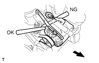
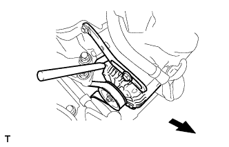
for Unleaded Gasoline Specification Vehicle: Insert an adjusting bar between the engine mounting bracket and generator assembly. Push the adjusting bar towards the vehicle front to adjust the generator V belt tension.
NOTICE:
Do not insert the adjusting bar between the camshaft timing oil control valve assembly and generator assembly. It could damage the camshaft timing oil control valve assembly.
for Leaded Gasoline Specification Vehicle: Insert the adjusting bar between the engine mounting bracket and generator assembly. Push the adjusting bar towards the vehicle front to adjust the generator V belt tension.
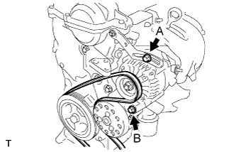
First tighten bolt A, then tighten bolt B.
Torque:
19 N*m{
189 kgf*cm
, 14 ft.*lbf
}
for bolt A
54 N*m{
551 kgf*cm
, 40 ft.*lbf
}
for bolt B
11.
INSPECT FAN AND GENERATOR V BELT
Check the V belt deflection and tension.
Deflection:
Item
Specified Condition
New belt
7.0 to 8.5 mm (0.28 to 0.33 in)
Used belt
11 to 13 mm (0.43 to 0.51 in)
Tension:
Item
Specified Condition
New belt
539 to 637 N (55 to 65 kg, 121 to 143 ld)
Used belt
245 to 392 N (25 to 40 kg, 55 to 88 ld)
If the belt deflection is not as specified, adjust it.
HINT:
Check the V belt deflection at the specified point.
Check the drive belt deflection at the specified point.
When installing a new belt, set its tension to the specified value.
When inspecting a belt which has been used for over 5 minutes, apply the Used Belt specifications.
When reinstalling a belt which has been used for over 5 minutes, adjust its deflection and tension to the intermediate values of each Used Belt specification.
V-ribbed belt tension and deflection should be checked after 2 revolutions of engine cranking.
When using a belt tension gauge, confirm its accuracy by using a master gauge first.
12.
INSTALL CYLINDER HEAD COVER SUB-ASSEMBLY (for RHD)
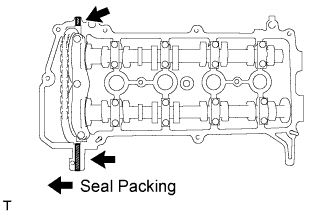
Apply seal packing to the cylinder head as shown in the illustration.
Seal Packing:
Part No. 08826-00080 or equivalent
NOTICE:
Remove any oil from the contact surface.
Install the cylinder head cover sub-assembly within 3 minutes of applying seal packing.
Do not start the engine within 2 hours of installation.
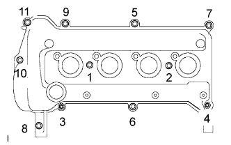
Install the cylinder head cover sub-assembly with the 9 bolts, 2 nuts and 2 seal washers.
Tighten the 9 bolts and 2 nuts in the sequence shown in the illustration.
Torque:
10 N*m{
102 kgf*cm
, 7.0 ft.*lbf
}
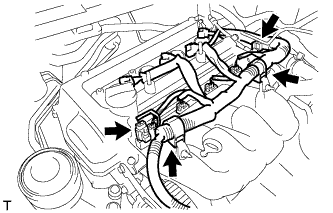
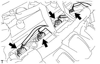
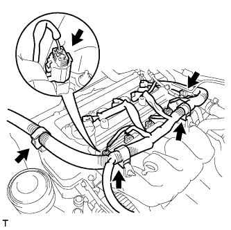
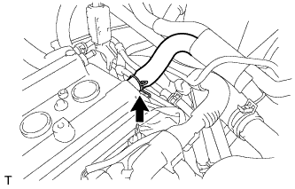
Connect the connector and wire harness clamp shown in the illustration and connect the engine wire harness.
Connect the fuel injector connectors.
13.
INSTALL CYLINDER HEAD COVER SUB-ASSEMBLY (for LHD)
Apply seal packing to the cylinder head as shown in the illustration.
Seal Packing:
Part No. 08826-00080 or the equivalent
NOTICE:
Remove any oil from the contact surface.
Install the cylinder head cover sub-assembly within 3 minutes of applying seal packing.
Do not start the engine for at least 2 hours after installation.
Install the cylinder head cover sub-assembly with the 9 bolts, 2 nuts and 2 seal washers.
Tighten the 9 bolts and 2 nuts in the sequence shown in the illustration.
Torque:
10 N*m{
102 kgf*cm
, 7.0 ft.*lbf
}
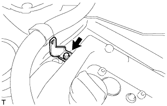
Install the wire harness bracket with the bolt.
Torque:
13 N*m{
133 kgf*cm
, 9.6 ft.*lbf
}
Connect the connector and wire harness clamp shown in the illustration and connect the engine wire harness.
Connect the fuel injector connectors.
14.
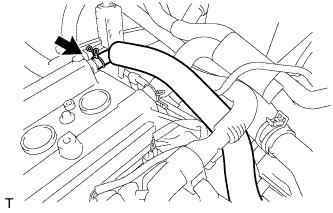
CONNECT VENTILATION HOSE NO. 2
Connect ventilation hose No. 2.
15.
CONNECT VENTILATION HOSE
Connect the ventilation hose.
16.
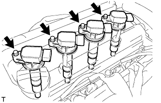
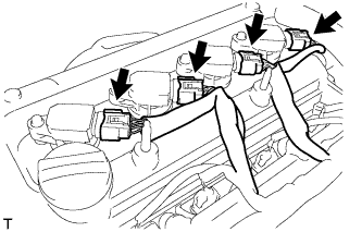
INSTALL IGNITION COIL NO. 1
Install the 4 ignition coils with the 4 bolts.
Torque:
9.0 N*m{
92 kgf*cm
, 80 in.*lbf
}
Connect the 4 ignition coil connectors.
17.
CONNECT CABLE TO NEGATIVE BATTERY TERMINAL
Torque:
5.4 N*m{
55 kgf*cm
, 48 in.*lbf
}
18.
CHECK FOR ENGINE OIL LEAKAGE
19.
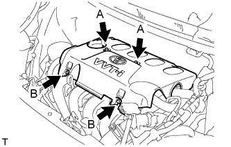
INSTALL CYLINDER HEAD COVER NO. 2
Tighten 2 A nuts, then 2 B nuts.
Torque:
7.0 N*m{
71 kgf*cm
, 62 in.*lbf
}
20.
INSTALL ENGINE UNDER COVER RH
21.
INSTALL ENGINE UNDER COVER SUB-ASSEMBLY (for Rough Road Area Specification Vehicles)