INSTALLATION
Removal / installation · Vehicles built from Aug 2005
| 1. INSTALL HEADLIGHT DIMMER SWITCH |

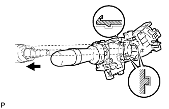  |
Engage the 2 claws and install the headlight dimmer switch, as shown in the illustration.
Install the headlight dimmer switch with the clamp.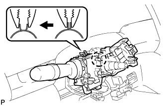
Connect the connector.
| 2. INSTALL WIPER SWITCH |
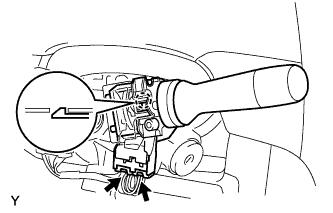 |
Engage the claw and install the windshield wiper switch.
Connect the 2 connectors.
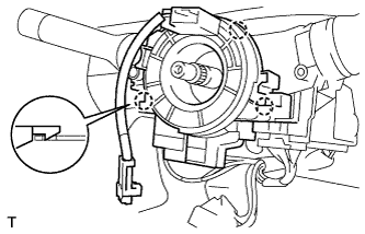
| 3. INSTALL SPIRAL CABLE (w/ Steering Sensor) |
 |
Check that the ignition switch is turned to off.
Confirm that the negative battery terminal is detached.
- CAUTION:
- Do not begin the operation for at least 90 seconds after the negative battery terminal is detached
Confirm that the front tires face straight forward.
Confirm that the turn signal switch is in the neutral position.
- NOTICE:
- Perform the operation when the turn signal switch is in the neutral position. Otherwise, the pin of the turn signal will break.
Engage the 3 claws and install the spiral cable.
- NOTICE:
- Pull the lock pin out before installing the steering wheel, when replacing the spiral cable with a new one.
Connect the steering connector.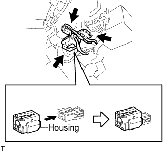
Connect the airbag connector.
Connect the horn connector.
| 4. INSTALL SPIRAL CABLE (w/o Steering Sensor) |
|
|
Check that the ignition switch is turned to off.
Confirm that the negative battery terminal is detached.
- CAUTION:
- Do not begin the operation for at least 90 seconds after the negative battery terminal is detached.
Confirm that the front tires face straight forward.
Confirm that the turn signal switch is in the neutral position.
- NOTICE:
- Perform the operation when the turn signal switch is in the neutral position. Otherwise, the pin of the turn signal will break.
Engage the 3 claws and install the spiral cable.
- NOTICE:
- Pull the lock pin out before installing the steering wheel, when replacing the spiral cable with a new one.
Connect the airbag connector.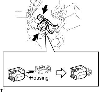
Connect the horn connector.
| 5. INSTALL STEERING COLUMN COVER |
Engage the claw to install the steering column upper cover.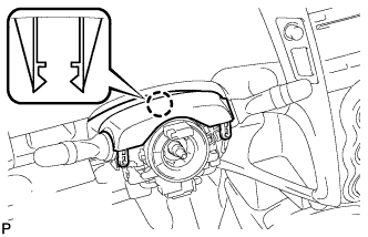
Engage the 2 claws to install the steering column lower cover.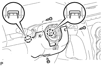
Install the 3 screws.
| 6. INSTALL STEERING COLUMN COVER SUPPORT (w/ Entry and Start System) |
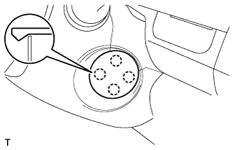 |
Engage the 4 claws to install the steering column cover support.
| 7. INSTALL STEERING WHEEL ASSEMBLY |
Align the matchmarks and install the steering wheel assembly onto the steering column assembly.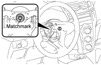
Install the nut.
- Torque:
- 50 N*m{ 510 kgf*cm , 37 ft.*lbf }
Connect all connectors to the spiral cable.
| 8. INSTALL STEERING PAD (w/ Steering Pad Switch) |
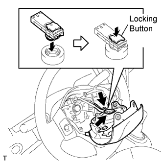 |
Connect the horn terminal.
Connect the airbag connector.
- NOTICE:
- Securely lock the locking button.
Install the steering pad.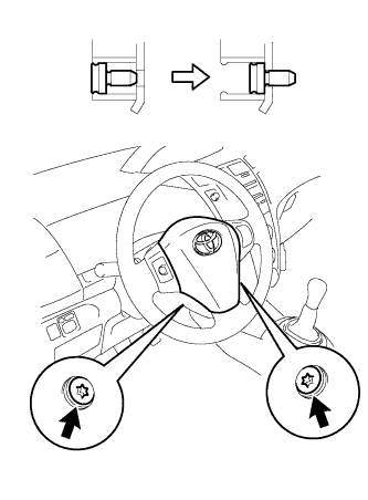
Using "Torx" socket wrench T30, tighten the 2 bolts.
- Torque:
- 8.8 N*m{ 90 kgf*cm , 78 in.*lbf }
- NOTICE:
- Tighten the 2 bolts while holding the steering pad to prevent it moving upward.
| 9. INSTALL STEERING PAD (w/o Steering Pad Switch) |
 |
- NOTICE:
- Do not use a steering pad that has been dropped.
Confirm that the ignition switch is turned to off.
Confirm that the negative battery terminal is detached.
- CAUTION:
- Do not begin the operation for at least 90 seconds after the negative battery terminal is detached.
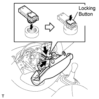
Connect the horn terminal.
Connect the airbag connector.
- NOTICE:
- Securely lock the locking button.
Install the steering pad.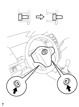
Using "Torx" socket wrench T30, tighten the 2 bolts.
- Torque:
- 8.8 N*m{ 90 kgf*cm , 78 in.*lbf }
- NOTICE:
- Tighten the 2 bolts while holding the steering pad to prevent it moving upward.
| 10. CONNECT CABLE TO NEGATIVE BATTERY TERMINAL |
- Torque:
- 5.4 N*m{ 55 kgf*cm , 48 in.*lbf }
| 11. INSPECT SRS WARNING LIGHT |