INSTALLATION
Removal / installation · Vehicles built from Aug 2005
| 1. INSTALL REAR DISC |

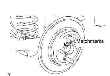  |
Align the matchmarks of the disc and axle hub and install the disc.
- NOTICE:
- When replacing the disc, select the position that gives the minimum disc runout.
| 2. INSTALL REAR DISC BRAKE CYLINDER MOUNTING |
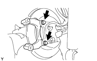 |
Install the disc brake cylinder mounting onto the axle beam with the 2 bolts.
- Torque:
- 57 N*m{ 585 kgf*cm , 42 ft.*lbf }
| 3. INSTALL REAR DISC BRAKE BUSH DUST BOOT |
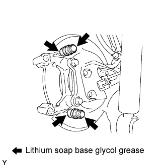 |
Apply lithium soap base glycol grease to 2 new dust boots.
Install the 2 dust boots onto the disc brake cylinder mounting.
| 4. INSTALL REAR DISC BRAKE CYLINDER SLIDE BUSH |
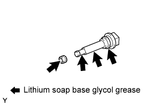 |
Apply lithium soap base glycol grease to the slide pins and a new slide bush, as shown in the illustration.
Install the slide bush onto the slide pin.
| 5. INSTALL REAR DISK BRAKE REAR CYLINDER SLIDE PIN |
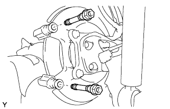 |
Install the 2 slide pins onto the cylinder mounting.
| 6. INSTALL REAR DISC BRAKE PAD SUPPORT PLATE |
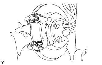 |
Install the 2 disc brake pad support plates onto the disc brake cylinder mounting.
| 7. INSTALL REAR DISC BRAKE ANTI SQUEAL SHIM KIT |
Install the anti squeal shim onto each brake pad.
| 8. INSTALL REAR DISC BRAKE PAD KIT (PAD ONLY) |
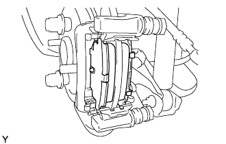 |
Install the 2 disc brake pads onto the disc brake cylinder mounting.
- NOTICE:
- There should be no oil or grease on the friction surfaces of the disc brake pads or the rear disc.
| 9. INSTALL REAR DISC BRAKE CYLINDER ASSEMBLY |
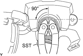 |
When reusing the pad, to counteract pad wear, use SST to turn the piston counterclockwise to the position where the protrusion portion of the pad does not protrude beyond the piston groove.
- SST
- 09960-10010
(09963-00400)
- NOTICE:
- Place the disc between the 2 brake pads and determine the piston return value.
Install the disc brake cylinder onto the disc brake cylinder mounting with the 2 bolts.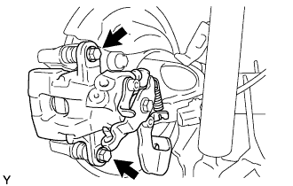
- Torque:
- 34 N*m{ 350 kgf*cm , 25 ft.*lbf }
| 10. INSTALL REAR FLEXIBLE HOSE |
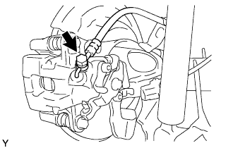 |
Install the flexible hose with the union bolt and a new gasket.
- Torque:
- 30 N*m{ 310 kgf*cm , 22 ft.*lbf }
- HINT:
- Install the flexible hose lock securely into the lock hole in the disc brake cylinder.
| 11. CONNECT PARKING BRAKE CABLE ASSEMBLY |
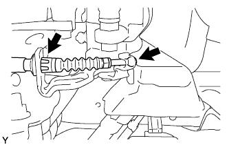 |
Install the casing cap clip onto the rear disc brake cylinder guide.
Connect the cable end to the rear disc brake cylinder operation lever.
| 12. FILL RESERVOIR WITH BRAKE FLUID |
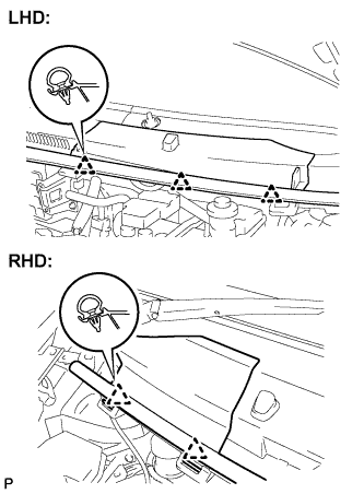 |
LHD:
Disengage the 3 clips and separate the hood to cowl top seal.
Remove the cowl top ventilator louver.
RHD:
Disengage the 2 clips and separate the hood to cowl top seal.
Remove the cowl top ventilator louver.
Set the brake fluid can upside down on the reservoir.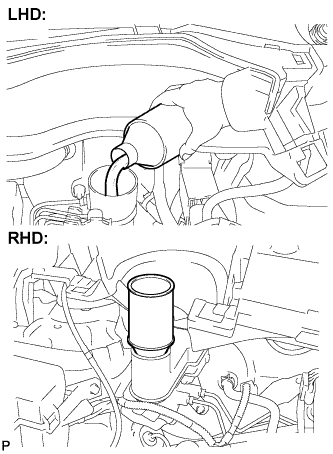
- Fluid:
- SAE J1703 or FMVSS No. 116 DOT3
- SAE J1704 or FMVSS No. 116 DOT4
| 13. BLEED MASTER CYLINDER |
- HINT:
- If the master cylinder has been disassembled or if the reservoir becomes empty, bleed the air from the master cylinder.
Using SST, disconnect the brake tubes from the master cylinder.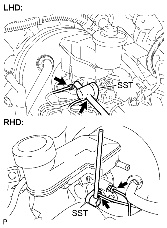
- SST
- 09023-00100
Slowly depress the brake pedal and hold it there (Step A).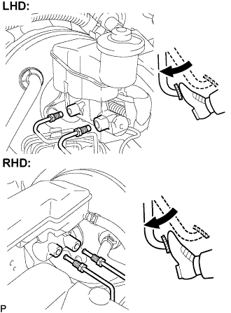
Block the outer holes with your fingers, and release the brake pedal (Step B).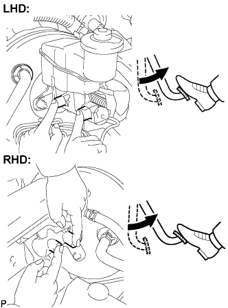
Repeat steps A and B 3 or 4 times.
Using SST, connect the brake tubes to the master cylinder.
- SST
- 09023-00100
- Torque:
- for use without SST:
- 15 N*m{ 155 kgf*cm , 11 ft.*lbf }
- for use with SST:
- 14 N*m{ 143 kgf*cm , 10 ft.*lbf }
- HINT:
- Use a torque wrench with a fulcrum length of 300 mm (11.81 in.).
- This torque value is effective when SST is parallel to a torque wrench.
- Use a torque wrench with a fulcrum length of 300 mm (11.81 in.).
| 14. BLEED BRAKE LINE |
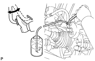 |
Connect the vinyl tube to the bleeder plug.
Depress the brake pedal several times, then loosen the bleeder plug with the pedal depressed (Step C).
At the point where the fluid stops coming out, tighten the bleeder plug, then release the brake pedal (Step D).
Repeat steps C and D until all the air in the fluid is completely bled out.
Tighten the bleeder plug.
- Torque:
- Front Disc and Rear Drum Brake:
- 8.3 N*m{ 85 kgf*cm , 73 in.*lbf }
- Rear Disc Brake:
- 11 N*m{ 112 kgf*cm , 8 ft.*lbf }
Repeat the above procedure to bleed the air out of the brake line for each wheel.
| 15. BLEED BRAKE ACTUATOR |
- NOTICE:
- After bleeding the air from the brake system, if the height or feel of the brake pedal cannot be obtained, perform air bleeding of the brake actuator with an intelligent tester by following the procedure below.
Depress the brake pedal more than 20 times with the engine off.
Connect the intelligent tester to the DLC3, and turn the ignition switch on (IG).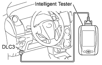
- NOTICE:
- Do not start the engine.
Select AIR BLEEDING on the intelligent tester.
- HINT:
- Refer to the intelligent tester operator's manual for further details.
Bleed the air out of the brake line when Step 1: Increase appears on the intelligent tester display.
- NOTICE:
- Bleed the air by following the steps displayed on the intelligent tester.
- Make sure that the master cylinder reservoir tank does not become empty of brake fluid.
- Bleed the air by following the steps displayed on the intelligent tester.
Connect the vinyl tube to either one of the bleeder plugs.
Depress the brake pedal several times, then loosen the bleeder plug connected to the vinyl tube with the pedal depressed (Step E).
When fluid stops coming out, tighten the bleeder plug and release the brake pedal (Step F).
Repeat steps E and F until all air in the fluid is completely bled out.
Tighten the bleeder plug completely.
- Torque:
- Front Disc and Rear Drum Brake:
- 8.3 N*m{ 85 kgf*cm , 73 in.*lbf }
- Rear Disc Brake:
- 11 N*m{ 112 kgf*cm , 8 ft.*lbf }
Repeat the above procedure for each wheel to bleed the air out of the brake line.
Bleed the air out of the suction line when Step 2: Inhalation appears on the intelligent tester display.
- NOTICE:
- Bleed the air by following the steps displayed on the intelligent tester.
- Make sure that the master cylinder reservoir tank does not become empty of brake fluid.
- Bleed the air by following the steps displayed on the intelligent tester.
Connect the vinyl tube to the bleeder plug at the right front wheel or the right rear wheel and loosen the bleeder plug.
Operate the brake actuator to bleed the air using the intelligent tester (Step G).
- NOTICE:
- Release the brake pedal at this time.
- HINT:
- This operation stops automatically after 4 seconds.
Check if the operation has stopped by referring to the intelligent tester display (Step H).
Repeat step G and H until all air in the fluid is completely bled out.
Tighten the bleeder plug.
- Torque:
- Front Disc and Rear Drum Brake:
- 8.3 N*m{ 85 kgf*cm , 73 in.*lbf }
- Rear Disc Brake:
- 11 N*m{ 112 kgf*cm , 8 ft.*lbf }
Repeat the above procedure for the other wheels to bleed the air out of the brake line.
Bleed the air out of the pressure reduction line when Step 3: Decrease appears on the intelligent tester display.
- NOTICE:
- Bleed the air by following the steps displayed on the the intelligent tester.
- Make sure that the master cylinder reservoir tank does not become empty of brake fluid.
- Bleed the air by following the steps displayed on the the intelligent tester.
Connect a vinyl tube to either one of the bleeder plugs.
Loosen the bleeder plug (Step I).
Using the intelligent tester, operate the brake actuator assembly, completely depress the brake pedal and hold it there.
- NOTICE:
- During this procedure, the pedal will feel heavy, but completely depress it so that the brake fluid comes out of the bleeder plug.
- Hold the brake pedal depressed. Do not depress and release the pedal repeatedly.
- During this procedure, the pedal will feel heavy, but completely depress it so that the brake fluid comes out of the bleeder plug.
- HINT:
- The operation stops automatically after 4 seconds. When performing this procedure continuously, set an interval of at least 20 seconds.
- When the operation is complete, the brake pedal goes down slightly. This is a normal phenomenon caused when the solenoid opens.
- The operation stops automatically after 4 seconds. When performing this procedure continuously, set an interval of at least 20 seconds.
Tighten the bleeder plug, then release the brake pedal (Step J).
Repeat step I and J until all the air in the fluid is completely bled out.
Tighten the bleeder plug.
- Torque:
- Front Disc and Rear Drum Brake:
- 8.3 N*m{ 85 kgf*cm , 73 in.*lbf }
- Rear Disc Brake:
- 11 N*m{ 112 kgf*cm , 8 ft.*lbf }
Repeat the above procedure for the other wheels to bleed the air out of the brake line.
Bleed the air out of the brake line again when Step 4: Increase appears on the intelligent tester display.
- NOTICE:
- Bleed the air by following the steps displayed on the intelligent tester.
- Make sure that the master cylinder reservoir tank does not become empty of brake fluid.
- Bleed the air by following the steps displayed on the intelligent tester.
Connect the vinyl tube to either one of the bleeder plugs.
Depress the brake pedal several times, then loosen the bleeder plug connected to the vinyl tube with the pedal depressed (Step K).
When fluid stops coming out, tighten the bleeder plug, then release the brake pedal (Step L).
Repeat steps K and L until all the air in the fluid is completely bled out.
Tighten the bleeder plug.
- Torque:
- Front Disc and Rear Drum Brake:
- 8.3 N*m{ 85 kgf*cm , 73 in.*lbf }
- Rear Disc Brake:
- 11 N*m{ 112 kgf*cm , 8 ft.*lbf }
Repeat the above procedure for the other wheels to bleed the air out of the brake line.
Make sure that the air bleeding is complete by referring to the intelligent tester display.
| 16. CHECK FLUID LEVEL IN RESERVOIR |
Check the fluid level and add fluid if necessary.
- Fluid:
- SAE J1703 or FMVSS No. 116 DOT3
- SAE J1704 or FMVSS No. 116 DOT4
| 17. CHECK FOR BRAKE FLUID LEAKAGE |
| 18. INSTALL REAR WHEEL |
- Torque:
- 103 N*m{ 1,050 kgf*cm , 76 ft.*lbf }
| 19. INSPECT PARKING BRAKE LEVER TRAVEL |
Slowly pull the parking brake lever to the fully applied position, counting the number of clicks.
- Parking brake lever travel at 200 N (20 kgf, 45 lbf):
Rear Brake Type
Number of clicks
Drum
6 to 9
Disc
4 to 7
| 20. ADJUST PARKING BRAKE LEVER TRAVEL |
Completely release the parking brake lever.
Loosen the lock nut and adjusting nut to completely release the parking brake cable.
Strongly step on the brake pedal 3 to 5 times with the engine stopped.
Turn the adjusting nut until the parking brake lever travel is corrected to within the specified range.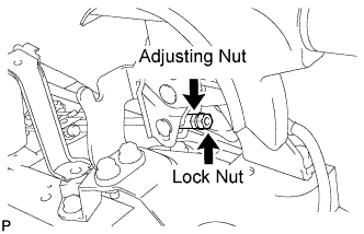
- Parking brake lever travel:
- 4 to 7 clicks at 200 N (20 kgf 45 lbf)
Tighten the lock nut.
- Torque:
- 5.4 N*m{ 55 kgf*cm , 48 in.*lbf }
Operate the parking brake lever 3 to 4 times, and check the parking brake lever travel.
Check whether the parking brake drags or not.
Release the parking brake lever and check that the clearance measurement between the rear disc brake cylinder operation lever and the stopper is within the specified range.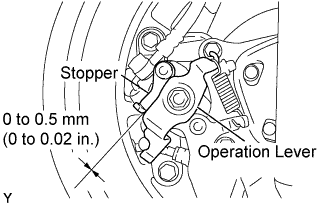
- Clearance:
- 0 to 0.5 mm (0 to 0.02 in.)
When operating the parking brake lever, check that the brake warning light illuminates.
- Standard:
- Brake warning light always illuminates at the first click.