INSTALLATION
Removal / installation · Vehicles built from Aug 2005
| 1.
INSTALL FUEL INJECTOR ASSEMBLY |
 |
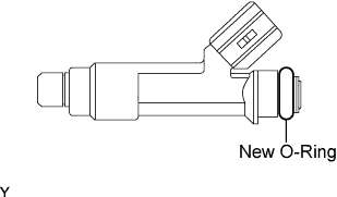
Apply a light coat of grease or gasoline to a new O-ring, and install it onto the injector.
Apply a light coat of grease or gasoline to the place where the delivery pipe touches the O-ring.
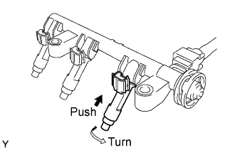
- Push the fuel injector while twisting it back and forth to install it in the fuel delivery pipe.
- NOTICE:
- Do not twist the O-ring.
- Check that the fuel injector turns smoothly after installing it. If it does not, reinstall it with a new O-ring.
Position the injector connectors so that they face upward.
| 2.
INSTALL FUEL DELIVERY PIPE |
|
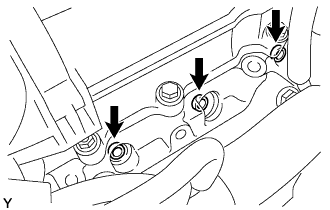
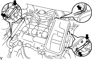
Install 3 new fuel injector vibration insulators to the cylinder head.
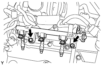
- Place the fuel delivery pipe and the 3 fuel injectors together to the cylinder head.
- NOTICE:
- Do not drop the fuel injectors when installing the fuel delivery pipe .
Provisionally install the 2 bolts which are used to hold the fuel delivery pipe to the cylinder head.
- NOTICE:
- Check that the fuel injector turns smoothly after installing it. If does not, reinstall it with a new O-ring.
Tighten the 2 bolts which are used to hold the fuel delivery pipe to the cylinder head.
-
Torque:
- 27 N*m{
275 kgf*cm
, 20 ft.*lbf
}
- Engage the 5 clamps and install the engine wire harness onto the cylinder head cover.
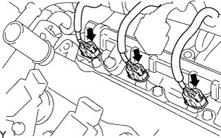
- Connect the 3 injector connectors.
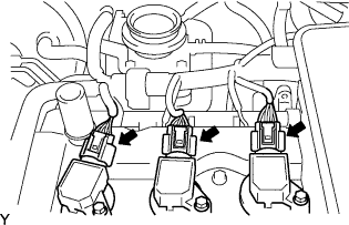
- Connect the 3 ignition coil connectors.
| 3.
INSTALL FUEL TUBE SUB-ASSEMBLY |
|
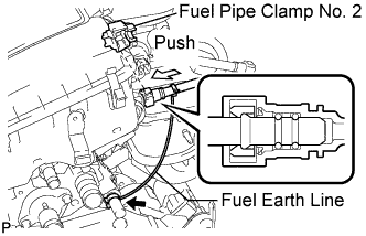
Push the tube connector into the pipe until the tube connector makes a "click" sound.
- NOTICE:
- Check whether there is any damage or foreign matter on the connected part of the fuel pipe.
- Check that the fuel tube connector and the pipe are securely connected by pulling on them after connecting.
Install fuel pipe clamp No. 2.
Connect the fuel earth line to the heater hose pipe.
| 4.
INSTALL AIR CLEANER FILTER ELEMENT SUB-ASSEMBLY
|
|
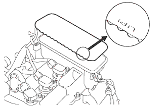
Install the air cleaner filter element as shown in the illustration.
| 5.
INSTALL AIR CLEANER CAP SUB-ASSEMBLY
|
|
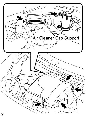
Install the air cleaner cap with the 2 clamps.
Tighten the 4 clamps.
| 6.
CONNECT CABLE TO NEGATIVE BATTERY TERMINAL |
|
-
Torque:
- 5.4 N*m{
55 kgf*cm
, 48 in.*lbf
}
| 7.
CHECK FOR FUEL LEAKAGE |
|