INSTALLATION
Removal / installation · Vehicles built from Aug 2005
| 1. INSTALL CLUTCH PEDAL STOPPER BOLT |

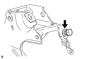  |
Install the clutch pedal stopper bolt and provisionally tighten the lock nut.
- HINT:
- Tighten the lock nut to the specified torque when adjusting the clutch pedal.
| 2. INSTALL CLUTCH START SWITCH ASSEMBLY |
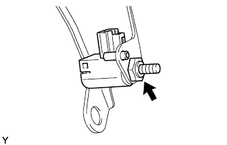 |
Install the clutch start switch with the nut.
- Torque:
- 16 N*m{ 160 kgf*cm , 12 ft.*lbf }
| 3. INSTALL CLUTCH PEDAL STOPPER |
| 4. INSTALL CLUTCH PEDAL PAD |
Install the clutch pedal pad onto the clutch pedal.
| 5. INSTALL CLUTCH MASTER CYLINDER PUSH ROD CLEVIS BUSH |
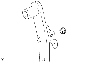 |
Apply MP grease to the inside of a new clevis bush.
Install the clevis bush onto the clutch pedal.
- HINT:
- Install the clevis bush from the right side of the vehicle.
| 6. INSTALL CLUTCH PEDAL NO.1 CUSHION |
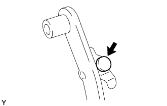 |
Install the clutch pedal No. 1 cushion onto the clutch pedal.
| 7. INSTALL CLUTCH PEDAL SHAFT COLLAR |
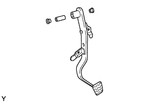 |
Apply MP grease to both sides of the 2 bushes and collar.
Install the 2 bushes and collar onto the clutch pedal.
| 8. INSTALL CLUTCH PEDAL SUB-ASSEMBLY |
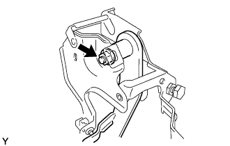 |
Install the clutch pedal onto the clutch pedal support with the bolt and the nut.
- Torque:
- 37 N*m{ 377 kgf*cm , 27 ft.*lbf }
| 9. INSTALL CLUTCH PEDAL SUPPORT SUB-ASSEMBLY |
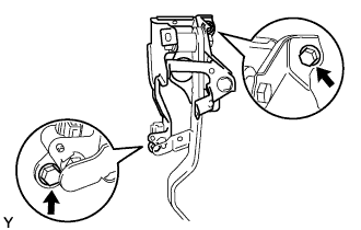 |
Install the clutch pedal support onto the vehicle with the 2 bolts.
- Torque:
- 9.0 N*m{ 92 kgf*cm , 80 in.*lbf }
| 10. INSTALL CLUTCH MASTER CYLINDER ASSEMBLY |
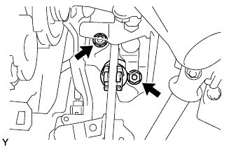 |
Install the clutch master cylinder with the 2 nuts.
- Torque:
- 9.0 N*m{ 92 kgf*cm , 80 in.*lbf }
Apply MP grease to the contact surface of the hole pin and clevis bush.
Connect the clevis to the clutch pedal with the hole pin.
- HINT:
- Install the hole pin from the right side of the vehicle.
Install the clip onto the hole pin.
| 11. CONNECT CABLE TO NEGATIVE BATTERY TERMINAL |
- Torque:
- 5.4 N*m{ 55 kgf*cm , 47 in.*lbf }
| 12. INSPECT AND ADJUST CLUTCH PEDAL SUB-ASSEMBLY |
Pull back the floor carpet.
Check that the pedal height is correct.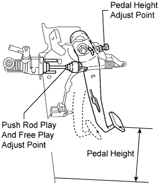
- Pedal height from floor:
- 144.4 to 154.4 mm (5.685 to 6.079 in.) 1KR-FE/2NZ-FE
- 159.2 to 169.2 mm (6.268 to 6.661 in.) 1NZ-FE
If the pedal height is not as specified, adjust it as follows.
Loosen the lock nut and turn the stopper bolt until the correct height is obtained.
Tighten the lock nut.
- Torque:
- 16 N*m{ 160 kgf*cm , 12 ft.*lbf }
| 13. INSPECT CLUTCH START SWITCH ASSEMBLY |
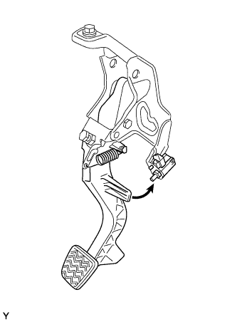 |
Check that the engine does not start when the clutch pedal is released.
Check that the engine starts when the clutch pedal is fully depressed.
If necessary, replace the clutch start switch assembly.
| 14. INSTALL INSTRUMENT UNDER COVER SUB-ASSEMBLY NO.1 |
Engage the 3 claws and install the instrument panel under cover.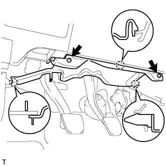
Tighten the 2 screws.