INSTALLATION
Removal / installation · Vehicles built from Nov 2005
| 1. INSTALL CLUTCH MASTER CYLINDER ASSEMBLY |

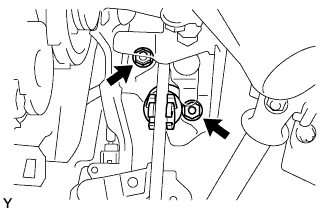  |
Install the clutch master cylinder with the 2 nuts.
- Torque:
- 9.0 N*m{ 92 kgf*cm , 80 in.*lbf }
Apply MP grease to the contact surface of the hole pin and clevis bush.
Connect the clevis to the clutch pedal with the hole pin.
- HINT:
- Install the hole pin from the right side of the vehicle.
Install the clip onto the hole pin.
| 2. INSTALL CLUTCH MASTER CYLINDER TO FLEXIBLE HOSE TUBE |
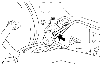 |
- SST
- 09023-00101
Using SST, connect the flexible hose tube.
- Torque:
- 15 N*m{ 153 kgf*cm , 11 ft.*lbf }
| 3. INSTALL CLUTCH RESERVOIR TUBE |
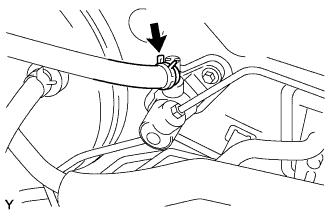 |
Connect the clutch reservoir tube to the clutch master cylinder with the clip.
| 4. ADD BRAKE FLUID |
| 5. BLEED CLUTCH PIPE LINE |
| 6. INSPECT BRAKE FLUID LEVEL |
| 7. INSPECT AND ADJUST CLUTCH PEDAL SUB-ASSEMBLY |
Pull back the floor carpet.
Check that the pedal height is correct.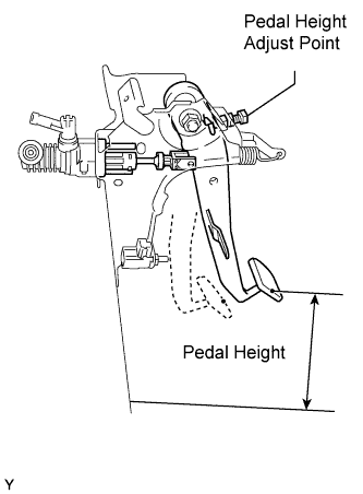
- Pedal height from floor:
- 149.2 to 159.2 mm (5.874 to 6.268 in.) 1KR-FE/2SZ-FE
- 159.3 to 169.3 mm (6.272 to 6.665 in.) 1ND-TV
If the pedal height is not as specified, adjust it as follows.
Loosen the lock nut and turn the stopper bolt until the correct height is obtained.
Tighten the lock nut.
- Torque:
- 16 N*m{ 160 kgf*cm , 12 ft.*lbf }
| 8. INSTALL INSTRUMENT PANEL UNDER COVER SUB-ASSEMBLY NO.1 |
Engage the 3 claws and install the instrument panel under cover.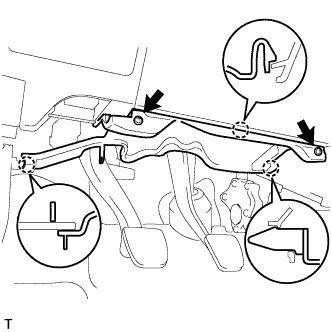
Tighten the 2 screws.