REMOVAL
Removal / installation · Vehicles built from Aug 2005
- HINT:
- Use the same procedure for both the RH and LH sides.
- The procedure described below is for the LH side.
- Use the same procedure for both the RH and LH sides.
| 1. DISCONNECT CABLE FROM NEGATIVE BATTERY TERMINAL |
| 2. REMOVE DOOR ARMREST COVER |

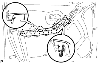  |
for 5 Door:
Using a screwdriver with its tip wrapped in protective tape, disengage the 8 claws and 3 clips and remove the door armrest cover.
for 3 Door: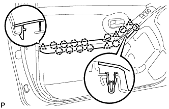
Disengage the 12 claws and 3 clips and remove the door armrest cover.
| 3. REMOVE FRONT ARMREST BASE PANEL UPPER |
|
|
for 5 Door:
Using a screwdriver with its tip wrapped in protective tape, disengage the 8 claws and 3 clips and remove the door armrest cover.
for 3 Door:
Disengage the 12 claws and 3 clips and remove the door armrest cover.
| 4. REMOVE FRONT DOOR TRIM BOARD SUB-ASSEMBLY |
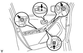 |
Remove the 4 screws.
5 Door: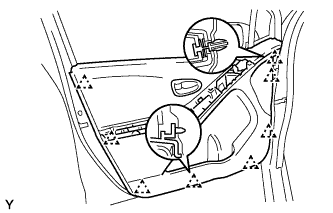
Disengage the 8 clips.
3 Door: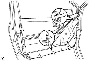
Disengage the 9 clips.
Disconnect the front door lock remote control cable and front door inside locking cable and remove the front door trim board.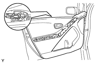
| 5. REMOVE FRONT DOOR INSIDE HANDLE SUB-ASSEMBLY |
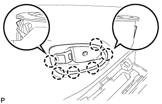 |
Disengage the 6 claws and remove the front door inside handle.
| 6. REMOVE FRONT DOOR WINDOW FRAME FRONT MOULDING |
Using an infrared light, heat the front door window frame front moulding.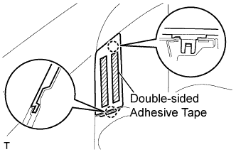
- CAUTION:
- Do not burn yourself with the heated front door panel or infrared light.
- HINT:
- Heat at 40 to 60 °C (104 to 140 °F) for 3 to 5 minutes.
Disengage the 2 claws and remove the double-sided adhesive tape and the front door window frame front moulding.
| 7. REMOVE FRONT DOOR WINDOW FRAME REAR MOULDING (for 3 Door) |
Using an infrared light, heat the front door window frame rear moulding.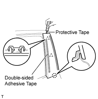
- NOTICE:
- Do not burn yourself with the heated front door panel or infrared light.
- HINT:
- Heat at 40 to 60°C (104 to 140°F) for 3 to 5 minutes.
Using a screwdriver with its tip wrapped in protective tape, disengage the 2 clips and the claw and remove the double-sided adhesive tape and front door window frame rear moulding.
| 8. REMOVE OUTER REAR VIEW MIRROR ASSEMBLY |
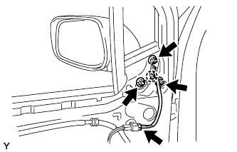 |
w/ Power mirror:
Disconnect the connector.
Remove the 3 nuts, disengage the claw and remove the outer rear view mirror.
| 9. REMOVE FRONT DOOR BELT MOULDING |
for 5 Door: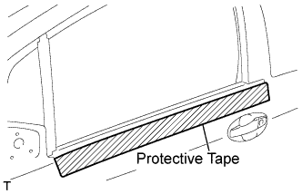
Apply protective tape to the door panel in the area around the front door belt moulding.
Using a moulding remover, disengage the 5 claws and the clip and remove the front door belt moulding.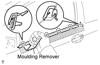
for 3 Door: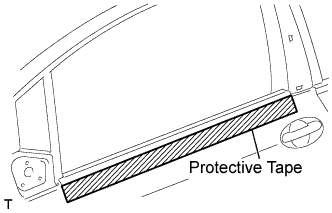
Apply protective tape to the door panel in the area around the front door moulding.
Using a moulding remover, disengage the 5 claws and remove the front door belt moulding.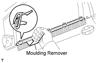
| 10. REMOVE FRONT DOOR SERVICE HOLE COVER |
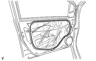 |
for 5 Door:
Disconnect the connectors and clamps, then remove the front door service hole cover.- NOTICE:
- Remove any tape remaining on the door side.
for 3 Door: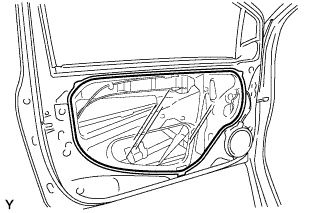
Disconnect the connectors and clamps, then remove the front door service hole cover.- NOTICE:
- Remove any tape remaining on the door side.
| 11. REMOVE FRONT DOOR GLASS SUB-ASSEMBLY |
Driver side:
Provisionally install the power window regulator master switch.
Passenger side:
Provisionally install the power window regulator switch.
Move the front door glass until the 2 bolts appear in the service holes.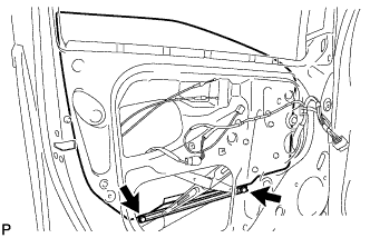
Remove the 2 bolts.
- NOTICE:
- Do not drop or damage the front door glass when removing the bolts.
Remove the front door glass in the direction indicated by the arrows in the illustration.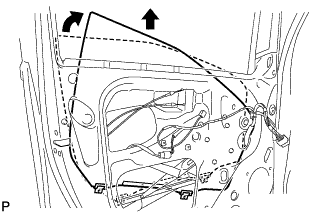
- NOTICE:
- Do not damage the glass.
Driver side:
Remove the power window regulator master switch.
Passenger side:
Remove the power window regulator switch.
| 12. REMOVE FRONT DOOR GLASS RUN |
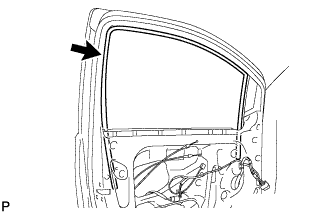 |
Remove the front door glass run.
| 13. REMOVE FRONT DOOR WINDOW REGULATOR SUB-ASSEMBLY |
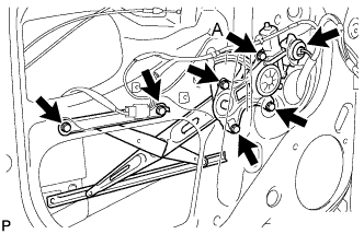 |
Disconnect the connector.
Loosen bolt A.
Remove the 5 bolts, then remove the front door window regulator.
- NOTICE:
- Do not drop or damage the window regulator when removing the bolts.
- HINT:
- Remove the window regulator through the service hole.
| 14. REMOVE FRONT DOOR FRAME SUB-ASSEMBLY REAR LOWER |
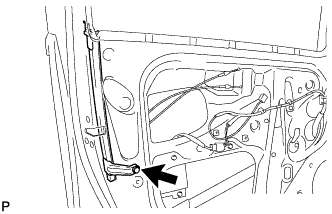 |
Remove the bolt, then remove the front door frame sub-assembly rear lower.
- NOTICE:
- Do not drop or damage the front door frame sub-assembly rear lower when removing the bolt.
- HINT:
- Remove the front door frame sub-assembly rear lower through the service hole.
| 15. REMOVE FRONT DOOR OUTSIDE HANDLE COVER |
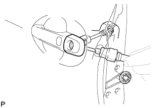 |
Remove the hole plug.
Using "Torx" socket wrench T30, loosen the screw and remove the cover with the door lock key cylinder installed.
| 16. REMOVE FRONT DOOR LOCK ASSEMBLY |
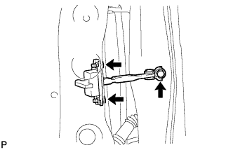 |
Remove the 3 bolts, then remove the front door check.
- NOTICE:
- Do not drop or damage the door check when removing the bolts.
- HINT:
- Remove the door check through the service hole.
| 17. REMOVE FRONT DOOR HANDLE ASSEMBLY OUTSIDE |
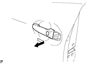 |
Disconnect the connector.
Remove the handle by sliding and pulling it in the direction indicated by the arrow mark in the illustration.
| 18. REMOVE BACK DOOR TRIM BOARD ASSEMBLY |
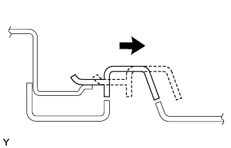 |
Using a screwdriver with its tip wrapped in protective tape, slide the handle plate of the back door trim board to disengage it.
Disengage the 3 claws and 9 clips and remove the back door trim board.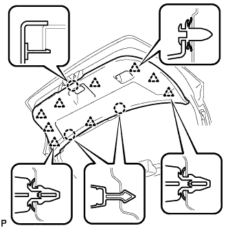
| 19. REMOVE BACK DOOR LOCK ASSEMBLY |
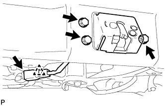 |
Disconnect the connector and the clamp.
Remove the 3 bolts and the back door lock.
| 20. REMOVE BACK DOOR OUTSIDE HANDLE |
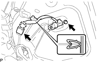 |
Disconnect the connector.
Disengage the claw and the clamp.
Remove the bolt and the back door outside handle.