INSTALLATION
Removal / installation · Vehicles built from Aug 2005
| 1. INSTALL POWER WINDOW REGULATOR MOTOR ASSEMBLY FRONT |

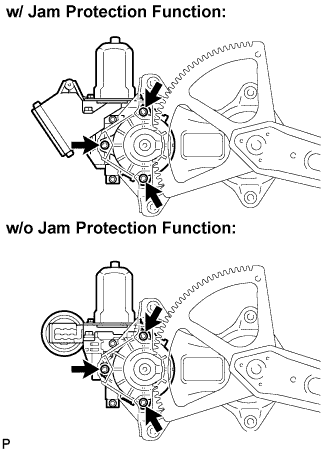  |
Apply MP grease to the sliding and rotating areas of the regulator motor.
Using "Torx" socket wrench T25, install the power window regulator motor assembly front with the 3 screws.
- Torque:
- 5.4 N*m{ 55 kgf*cm , 48 in.*lbf }
| 2. INSTALL FRONT DOOR WINDOW REGULATOR SUB-ASSEMBLY |
Apply MP grease to the sliding and rotating areas of the front door window regulator.
- NOTICE:
- Do not apply grease to the window regulator spring.
Loosely screw bolt A onto the front door window regulator.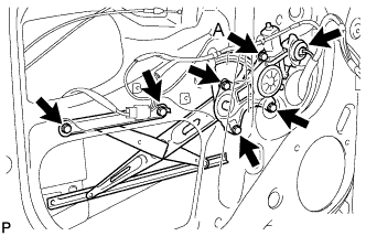
Insert the front door window regulator into the door panel. Use bolt A to hang the front door window regulator on the door panel.
- NOTICE:
- Do not drop the window regulator as it may be damaged.
Install the front door window regulator with the 5 bolts, and tighten bolt A.
- Torque:
- 8.0 N*m{ 82 kgf*cm , 71 in.*lbf }
Connect the connector.
| 3. INSTALL FRONT DOOR GLASS SUB-ASSEMBLY |
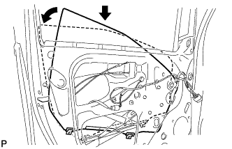 |
Insert the door glass into the door panel along the glass run as indicated by the arrows in the illustration.
- NOTICE:
- Do not damage the glass.
Install the front door glass onto the front door window regulator with the 2 bolts.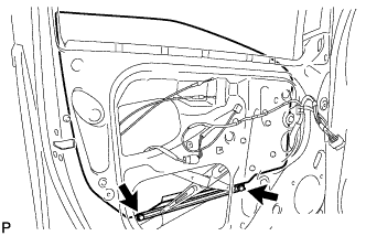
- Torque:
- 8.0 N*m{ 82 kgf*cm , 71 in.*lbf }
| 4. INSTALL FRONT DOOR SERVICE HOLE COVER |
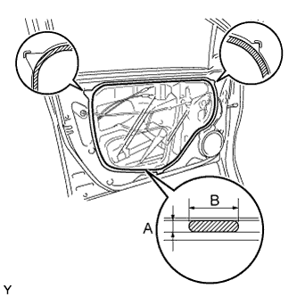 |
for 5 Door:
Apply butyl tape to the door panel, then install the front door service hole cover as shown in the illustration.- Adhesive:
- Part No. 08850-00065, Butyl Tape Set or the equivalent
- Specification:
Area
Dimension
A
2.0mm (0.079 in.) or more
B
6.0mm (0.236 in.) or more
- HINT:
- When installing the service hole cover, pull the links and connectors out through the service hole.
- There should be no wrinkles or folds after attaching the service hole cover.
- After attaching the service hole cover, check the quality of the seal.
- When installing the service hole cover, pull the links and connectors out through the service hole.
for 3 Door: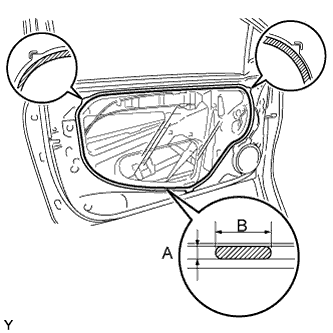
Apply butyl tape to the door panel, then install the front door service hole cover as shown in the illustration.- Adhesive:
- Part No. 08850-00065, Butyl Tape Set or the equivalent
- Specification:
Area
Dimension
A
2.0mm (0.079 in.) or more
B
6.0mm (0.236 in.) or more
- HINT:
- When installing the service hole cover, pull the links and connectors out through the service hole.
- There should be no wrinkles or folds after attaching the service hole cover.
- After attaching the service hole cover, check the quality of the seal.
- When installing the service hole cover, pull the links and connectors out through the service hole.
| 5. INSTALL FRONT DOOR BELT MOULDING |
for 5 Door: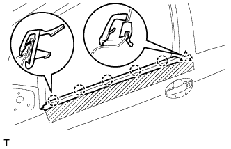
Engage the 5 claws and the clip and install a new front door belt moulding.
Remove the protective tape.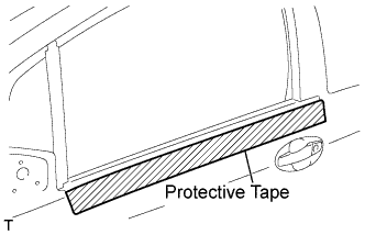
for 3 Door: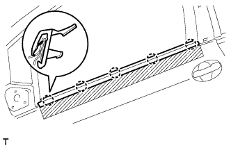
Engage the 5 claws and the clip and install a new front door belt moulding.
Remove the protective tape.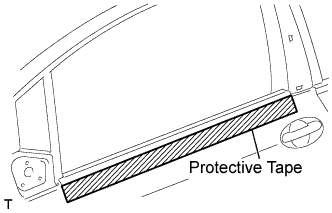
| 6. INSTALL OUTER REAR VIEW MIRROR ASSEMBLY |
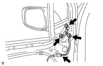 |
Engage the claw, then install the outer rear view mirror with the 3 nuts.
- Torque:
- 8.0 N*m{ 82 kgf*cm , 71 in.*lbf }
w/ Power mirror:
Connect the connector.
| 7. INSTALL FRONT DOOR WINDOW FRAME REAR MOULDING (for 3 Door) |
Clean the attachment surface.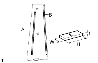
Using an infrared light, heat the adhesive remaining on the body.
- NOTICE:
- Do not burn yourself with the heated body or infrared light.
Using a shop rag or piece of cloth, rub the remaining adhesive off the body.
Using a non-residue solvent, clean the attachment surface.
Apply new double-sided adhesive tape to the front door window frame rear moulding.
Tape size: Area
t
W
H
A
0.8 mm (0.032 in.)
5 mm (0.197 in.)
340 mm (13.386 in.)
B
0.8 mm (0.032 in.)
5 mm (0.197 in.)
376 mm (14.803 in.)
Engage the 2 clips and the claw and install the front door window frame rear moulding.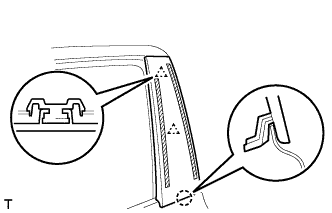
| 8. INSTALL FRONT DOOR WINDOW FRAME FRONT MOULDING |
Clean the attachment surface.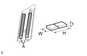
Using an infrared light, heat the adhesive remaining on the body.
- NOTICE:
- Do not burn yourself with the heated body or infrared light.
Using a shop rag or piece of cloth, rub the remaining adhesive off the body.
Using a non-residue solvent, clean the attachment surface.
Apply new double-sided adhesive tape to the front door window frame front moulding.
Tape size: Area
t
W
H
A
1.2 mm (0.047 in.)
7 mm (0.276 in.)
88 mm (3.465 in.)
Engage the 2 clips and the claw and install the front door window frame front moulding.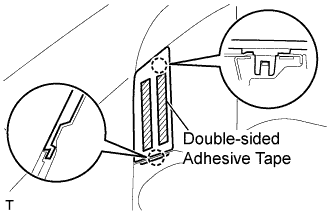
| 9. INSTALL FRONT DOOR TRIM BOARD SUB-ASSEMBLY |
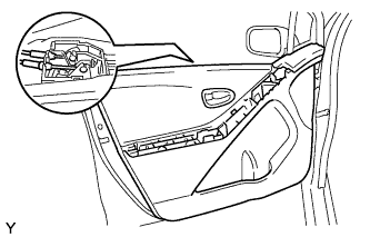 |
Connect the front door lock remote control cable and front door inside locking cable.
5 Door: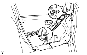
Engage the 8 clips and install the front door trim board.
3 Door: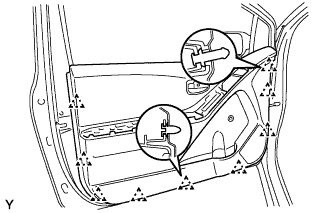
Engage the 9 clips and install the front door trim board.
Tighten the 4 screws.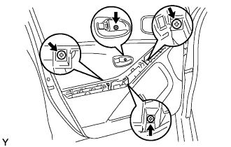
| 10. INSTALL FRONT ARMREST BASE PANEL UPPER |
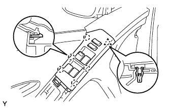 |
Connect the connector.
Engage the 5 claws and clip and install the front armrest base panel upper.
| 11. INSTALL DOOR ARMREST COVER |
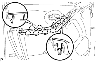 |
for 5 Door:
Engage the 8 claws and 3 clips and install the door armrest cover.
for 3 Door: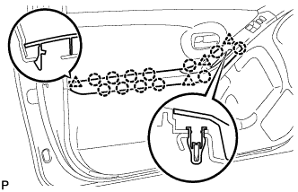
Engage the 12 claws and 4 clips and install the door armrest cover.
| 12. CONNECT CABLE TO NEGATIVE BATTERY TERMINAL |
- Torque:
- 5.4 N*m{ 55 kgf*cm , 48 in.*lbf }