INSTALLATION
Removal / installation · Vehicles built from Jan 2006
| 1. INSPECT AND ADJUST BRAKE BOOSTER PUSH ROD |

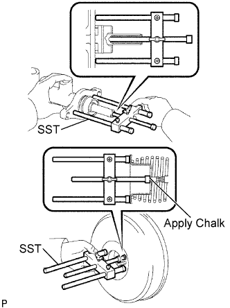  |
Set SST on the master cylinder and lower the rod of SST until it just touches the piston.
- SST
- 09737-00013
- HINT:
- SST: 09737-00012 can also be used.
Apply chalk to the flat tip of the SST rod. Turn SST upside down and measure the clearance between the brake booster push rod and SST.
- Standard Clearance:
- -0.21 to 0 mm (-0.0083 to 0 in.)
If the clearance is not within the standard, adjust the length by holding the rod using SST and turning the tip of the rod using a 7 mm socket driver.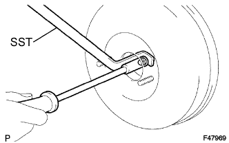
- SST
- 09737-00020
- NOTICE:
- Check the push rod clearance again after adjusting.
| 2. INSTALL BRAKE MASTER CYLINDER |
Install a new O-ring onto the brake master cylinder.
w/ ABS: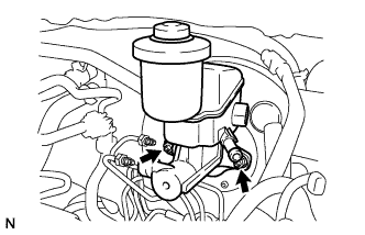
Install the brake master cylinder with the 2 nuts.
- Torque:
- 13 N*m{ 127 kgf*cm , 9 ft.*lbf }
w/o ABS: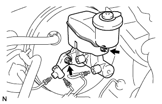
Install the brake master cylinder and brake tube way with the 2 nuts.
- Torque:
- 13 N*m{ 127 kgf*cm , 9 ft.*lbf }
Using SST, install the 2 brake tubes onto the brake master cylinder.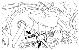
- SST
- 09023-00100
- Torque:
- for use without SST:
- 15 N*m{ 155 kgf*cm , 11 ft.*lbf }
- for use with SST:
- 14 N*m{ 143 kgf*cm , 10 ft.*lbf }
- HINT:
- Use a torque wrench with a fulcrum length of 300 mm (11.81 in.).
- This torque value is effective when SST is parallel to a torque wrench.
- Use a torque wrench with a fulcrum length of 300 mm (11.81 in.).
w/o ABS: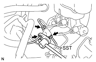
Using SST, install the 3 brake tubes to the brake tube way.
- SST
- 09023-00100
- Torque:
- for use without SST:
- 15 N*m{ 155 kgf*cm , 11 ft.*lbf }
- for use with SST:
- 14 N*m{ 143 kgf*cm , 10 ft.*lbf }
- HINT:
- Use a torque wrench with a fulcrum length of 300 mm (11.81 in.).
- This torque value is effective when SST is parallel to a torque wrench.
- Use a torque wrench with a fulcrum length of 300 mm (11.81 in.).
Connect the brake fluid level warning switch connector.
| 3. CONNECT CLUTCH RESERVOIR TUBE (for Manual Transaxle) |
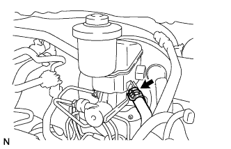 |
Connect the reservoir tube with the clip.
| 4. INSTALL BATTERY CARRIER |
- Torque:
- 17 N*m{ 175 kgf*cm , 13 ft.*lbf }
| 5. INSTALL BATTERY TRAY |
| 6. INSTALL BATTERY |
| 7. FILL RESERVOIR WITH BRAKE FLUID |
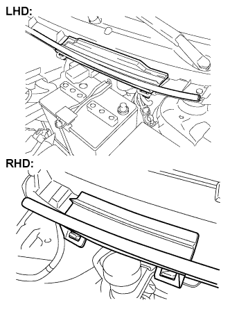 |
Remove the cowl top No. 2 ventilator louver center.
Set the brake fluid can upside down on the reservoir.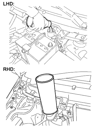
- Fluid:
- SAE J1703 or FMVSS No. 116 DOT3
- SAE J1704 or FMVSS No. 116 DOT4
| 8. BLEED MASTER CYLINDER |
- HINT:
- If the master cylinder has been disassembled or if the reservoir becomes empty, bleed the air from the master cylinder.
Using SST, disconnect the brake tubes from the master cylinder.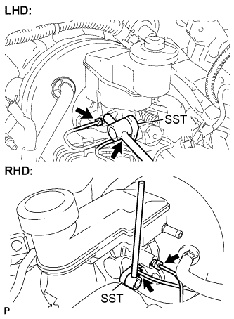
- SST
- 09023-00100
Slowly depress the brake pedal and hold it there (Step A).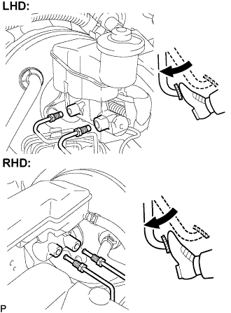
Block the outer holes with your fingers, and release the brake pedal (Step B).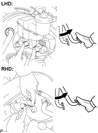
Repeat steps A and B 3 or 4 times.
Using SST, connect the brake tubes to the master cylinder.
- SST
- 09023-00100
- Torque:
- for use without SST:
- 15 N*m{ 155 kgf*cm , 11 ft.*lbf }
- for use with SST:
- 14 N*m{ 143 kgf*cm , 10 ft.*lbf }
- HINT:
- Use a torque wrench with a fulcrum length of 300 mm (11.81 in.).
- This torque value is effective when SST is parallel to a torque wrench.
- Use a torque wrench with a fulcrum length of 300 mm (11.81 in.).
| 9. BLEED BRAKE LINE |
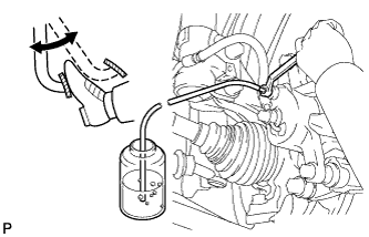 |
Connect the vinyl tube to the bleeder plug.
Depress the brake pedal several times, then loosen the bleeder plug with the pedal depressed (Step C).
At the point where the fluid stops coming out, tighten the bleeder plug, then release the brake pedal (Step D).
Repeat steps C and D until all the air in the fluid is completely bled out.
Tighten the bleeder plug.
- Torque:
- 8.3 N*m{ 85 kgf*cm , 73 in.*lbf }
Repeat the above procedure to bleed the air out of the brake line for each wheel.
| 10. CHECK FLUID LEVEL IN RESERVOIR |
Check the fluid level and add fluid if necessary.
- Fluid:
- SAE J1703 or FMVSS No. 116 DOT3
- SAE J1704 or FMVSS No. 116 DOT4
| 11. CHECK FOR BRAKE FLUID LEAKAGE |